
TM 5-3805-294-23-4
0624
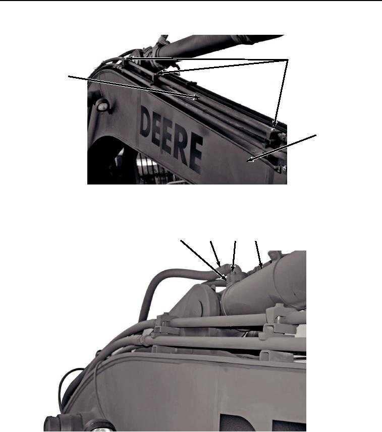
INSTALLATION - Continued
18, 19, 20
21
1
HYEX03559
Figure 13. Line Installation.
14.
Lightly lubricate O-ring (Figure 14, Item 17) with clean oil.
15
16, 17
14
2
HYEX03446
Figure 14. Hose and Clamp Halves Installation.
15.
Install hose (Figure 14, Item 16) and O-ring (figure 14, Item 17) to arm cylinder (Figure 14, Item 2) with two
clamp halves (Figure 14, Item 15) and four screws (Figure 14, Item 14).
16.
Tighten four screws (Figure 14, Item 14) to 130 lb-ft (176 Nm).
17.
Install hose (Figure 15, Item 12) to line (Figure 15, Item 13).