
TM 5-3805-294-23-4
0624
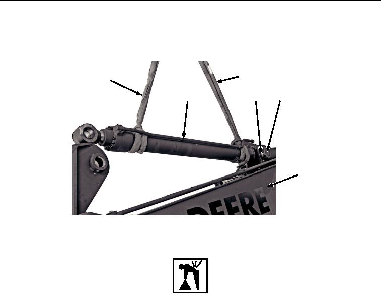
REMOVAL - Continued
21.
Remove two nuts (Figure 9, Item 23) and bolt (Figure 9, Item 24) from boom (Figure 9, Item 1) and pin (Figure
9, Item 22).
5
5
2
23, 24
22
1
HYEX03452
Figure 9. Arm Cylinder Removal.
WARNING
Arm cylinder weighs 640 lb (290 kg). Do not attempt to lift or move arm cylinder without the
aid of an assistant and suitable lifting device. Failure to comply may result in injury or death
to personnel.
22.
With the aid of an assistant and suitable lifting device (Figure 9, Item 5), raise arm cylinder (Figure 9, Item 2)
enough to relieve pressure from pin (Figure 9, Item 22).
23.
Remove pin (Figure 9, Item 22) from boom (Figure 9, Item 1) and arm cylinder (Figure 9, Item 2).
24.
With the aid of an assistant and suitable lifting device (Figure 9, Item 5), remove arm cylinder (Figure 9, Item
2) from boom (Figure 9, Item 1) and place on suitable stand.
25.
Remove suitable lifting device (Figure 9, Item 5) from arm cylinder (Figure 9, Item 2).
26.
Remove two shims (Figure 10, Item 25) and seals (Figure 10, Item 26) from arm cylinder (Figure 10, Item 2).
Discard seals.