
TM 5-3805-294-23-4
0625
INSTALLATION - Continued
NOTE
Install tie wraps as required.
1.
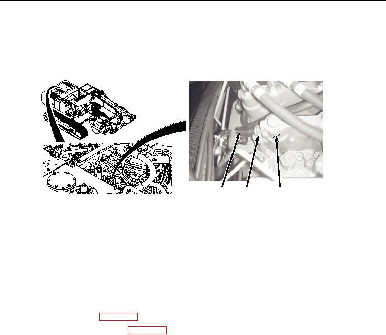
Lightly lubricate O-ring (Figure 2, Item 3) with clean oil.
1
2, 3
4
HYEX00969
Figure 2.
Arm In Pressure Sensor Installation.
2.
Install O-ring (Figure 2, Item 3) to arm in pressure sensor (Figure 2, Item 2).
3.
Install arm in pressure sensor (Figure 2, Item 2) and O-ring (Figure 2, Item 3) to main control valve (Figure 2,
Item 4).
4.
Connect wire harness connector B31 (1) to arm in pressure sensor (2).
END OF TASK
FOLLOW-ON MAINTENANCE:
1.
Install center top cover. (WP 0589)
2.
Connect negative battery cable. (WP 0521)
3.
Perform the Standard Follow-On Maintenance Instructions. (Volume 3, WP 0384)
END OF TASK
END OF WORK PACKAGE