TM 5-2420-230-24-1
10-6. HYDRAULIC PRESSURE TESTING.
This Task Covers:
a. Testing
b. Follow-On Maintenance
INITIAL SETUP
Test Equipment
Equipment Conditions
Gauge, pressure, capable of measuring 0 to 3,500 psi
TM or Para
Condition Description
(0 to 24 132 kPa)
Spare tire and carrier assembly
removed.
Tools and Special Tools
FEL and backhoe travel stops
Hydraulic valve manual override lever, BII,
deployed.
Engine access panel removed
Tool kit, general mechanics, Item 38, Appendix B
(if required).
Tool outfit, HSTRU, Item 40.1, Appendix B
Drawings Required
Materials/Parts
None
None
Estimated Time to Complete
Personnel Required
Refer to MAC in Appendix B
MOS 62B, Construction Equipment Repairer (2)
References
FO-4, Hydraulic schematic
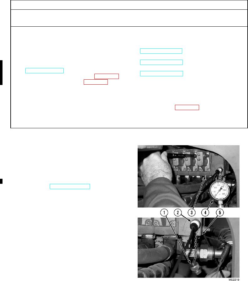
a. Testing.
(1)
Remove cap (1) from test port (2) on backhoe
valve block (3).
(2)
Install gauge (4) on test port (2).
(3)
Start engine and ensure engine speed is at idle
and hydraulic master switch is in OFF
position (TM 5-2420-230-10).
(4)
Use hydraulic valve manual override lever to
stall out backhoe bucket hydraulic circuit on
backhoe valve block (3).
(5)
Observe gauge (4). Gauge should read
3,000 psi (20 684 kPa).
NOTE
Backhoe relief valve only requires small
amount of rotation to properly adjust
hydraulic pressure.
Turning backhoe relief valve clockwise
increases hydraulic pressure and turning
counterclockwise lowers the pressure.
(6)
If pressure is not 3,000 psi (20 684 kPa), use 6-mm Allen wrench to rotate backhoe relief valve (5) until the correct
pressure is displayed on gauge (4).
Change 1

