
TM 5-2420-230-24-1
Maintenance & Service Manual
R & HR32000 3 & 6 Speed LD
MAINTENANCE AND SERVICE
The instructions contained herein cover the dis-
assemblies may vary on specific models. The units are very
assembly and reassembly of the transmission in a sequence
similar to trouble shoot, disassemble, repair and re-
that would normally be followed after the unit has been
assemble.
removed from the machine and is to be completely
CAUTION: Cleanliness is of extreme importance and
overhauled. It must also be understood that this is a basic
an absolute must in the repair and overhaul of this unit.
32000 transmission with may option.
Companion
Before attempting any repairs, the exterior of the unit must
flanges and output shafts with and without disconnect
be thoroughly cleaned to prevent the possibility of dirt and
foreign matter entering the mechanism.
DISASSEMBLY
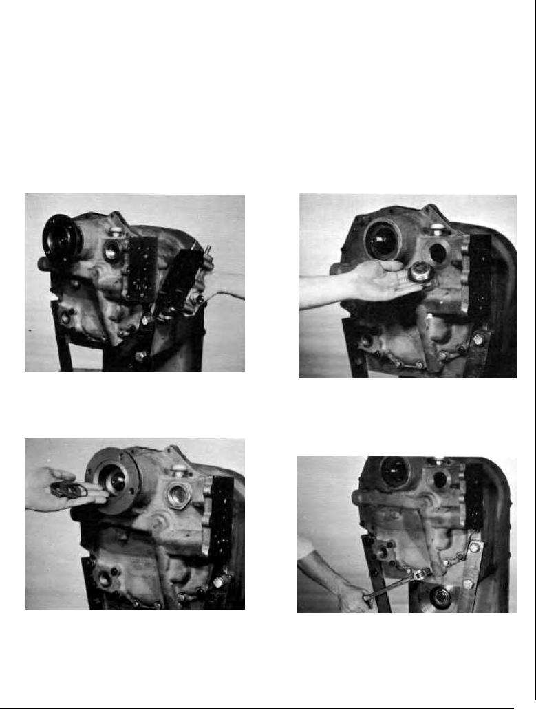
Figure 1
Figure 3
Remove control valve bolts and washers. Remove control valve.
Remove front cover plug.
Use caution as not to lose detent springs and bolts.
Figure 2
Figure 4
Remove companion flange nut, washer and "O" ring.
Remove bolts securing front cover to transmission housing.
--74--
F-119