
TM 5-2420-230-24-1
Spicer Speciality Axle Division - Technical Publications
SECTION 10
BRAKE SHOE ASSEMBLY
10.1
Using service tool no. E320 or other suitable bumper tool, fit two brake shoe bushes (49) into one of
brake shoes (48) and flush with inner faces of lugs.
10.2
Repeat operation 10.1 for other brake shoe (48).
10.3
If new liners (37) are to be fitted, proceed as follows :-
For ease of assembly ensure that different sizes of rivets are stored in separate containers.
a)
Place brake shoe (48) outer face uppermost, on bench.
b)
Position first liner (37) on shoes and locate in place by fitting rivets (39),
in centre line of holes (4 off).
Then fit rivets (39) into outer lines of holes (8 off).
Repeat for second liner half (37).
c)
Tap rivets (39) fully home using a suitable drift and hammer.
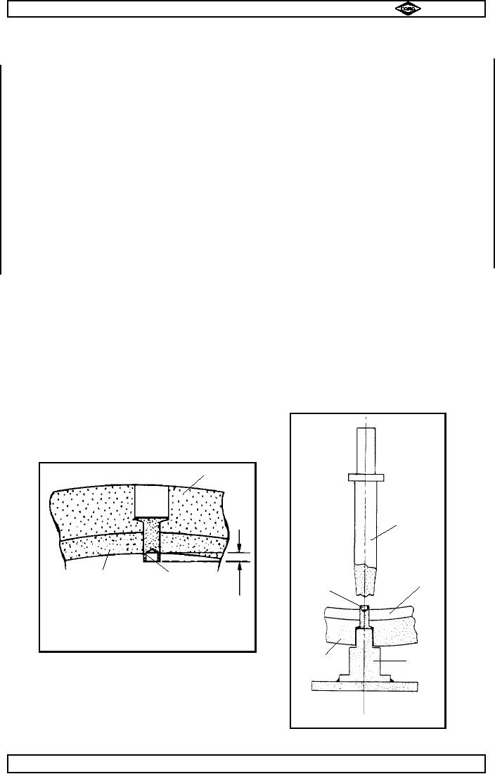
d)
Turn brake shoe (48) onto its side and check amount of rivet (39) protrusion from inner
curved face of brake shoe.
Correct protrusion 'P' is between 3mm & 7.5mm. See fig.no. 6.
Note :-
If any holes are fitted with rivets (39) and they protrude MORE THAN
7.5mm, then either brake shoe and / or liner are defective and must be replaced.
When all rivets protrude correct amount, insert a thin, 1/64 " dia (4.4mm) max,
screwdriver or steel rod into end of each rivet (39) in turn and lever sideways to slightly
deform end of rivets.
This retains rivets in position during final peening operation.
e)
Place assembled shoe, liners underneath, on riveting machine or suitable hand
equipment (see fig. no. 7) and peen over rivets to secure liners (37) to brake shoe.
Note :-
Due to limited access, centre rivets will have to be peened using hand peening
equipment.
f)
After riveting check brake shoe to liner clearance, using feeler gauges.
Permissable clearance is 0.000" to 0.004" (0.0 to 0.102mm).
TP37
TP36
Item (37)
●
Punch
●
●
●
Item (48)
Item (39)
Item (48)
'P
Item (39)
Dim.'P' is between
3mm & 7.5mm
●
●
Fig No 6.
●
Anvil
Item (37)
●
Fig No 7
Spicer Speciality Axle Division
Page No.B9
Manual No. 1785 Issue B
A
J-39