
TM 5-2420-230-24-1
Spicer Speciality Axle Division - Technical Publications
STEERING HEAD AND AXLE STUB
SECTION 12
REMOVAL OF STEERING HEAD ASSEMBLY
12.1
Take out ball socket split pin (132 & 138) then remove ball socket nut (131 & 137)
along with washer (133 & 139).
12.2
Using a suitable ball pin extractor, remove ball socket assembly (122 & 124)
from bottom steering lever (127 & 135).
Note :-
When separating ball joint from steering lever, an extractor tool MUST be used. DO
NOT strike areas around ball pin tapers with hammer blows under any circumstances
due to possible ball pin taper deformation.
12.3
Loosen swivel top cap setscrews (80) to release pressure in steering head. Remove one of setscrews
along with its washer (79) and replace with an eye bolt.
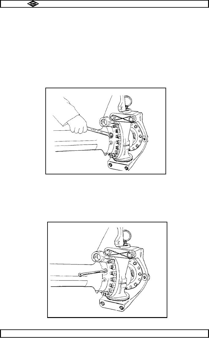
12.4
Remove U.J. fork oil seal housing lockscrew nuts (115). See fig no.12.
TP44
Fig No 12
12.5
Remove U.J. fork oil seal housing lockscrews (114). See fig no. 13.
TP45
Fig No 13
Spicer Speciality Axle Division
Manual No. 1785 Issue A
Page No.B12
J-42