TM 5-2420-230-24-1
Spicer Speciality Axle Division - Technical Publications
SECTION 10
BRAKE SHOE ASSEMBLY Cont.
10.4
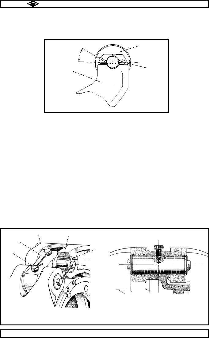
Smear bore of one of brake shoe rollers (33) with grease (BP Energrease AS11 or equivalent). Locate
roller (33) in position, fit brake shoe roller pin (36) so that headed portion will be towards brake
bracket (44) when fitted. Secure in place with brake shoe roller pin split pin (32). Splay pin (32) to
TP38
Item (33)
●
30
●
Item (48)
Item (32)
●
Fig.No.8
10.5
Repeat operation 10.4 for other brake shoe assembly.
SECTION 11
FINAL ASSEMBLY OF BRAKE Ref Fig 9.
11.1
Wipe clean inner surfaces of brake shoe bushes (49) and smear with BP Keenomax L2 or equivalent
high melting point grease. Ensure all indentations are full.
11.2
Fit brake shoe to brake bracket as follows:-
a)
Assemble a brake shoe pivot setscrew washer (43) and a brake shoe pivot bush setscrew
(42) together, then screw into one end of a brake shoe pivot pin (46), finger tight.
b)
Position first brake shoe (48) on brake bracket (44). Insert partially assembled pivot pin
in pivot pin hole either side of brake shoe, passing through brake bracket and into other
bushed hole as shown.
c)
Using pivot pin setscrew (42), rotate pivot pin until countersunk hole in pivot pin is in line
with threaded hole on brake bracket (44).
d)
Screw a brake shoe pivot pin lockscrew (45) into threaded hole in brake bracket (44) to
locate in countersunk hole in pivot pin (46), thus locking pivot pin then tighten
lockscrew (45).
Note :- Care must be taken during this operation as misalignment can cause brake drum
obstruction.
e)
Fit second brake shoe pivot pin (46).
f)
Repeat above operations for other brake shoe assembly.
11.3
When both brake shoe assemblies are fitted, secure lockscrews (45) and pivot pin setscrews (42) with
18SWG (1.25mm) lockwire as shown.
TP40
TP39
Item (49)
Item (48)
Item (44)
●
Item (46)
Item (45)
●
Item (43)
●
●
●
Item (42)
●
●
Cross section through dry pivot pin assembly
showing bush arrangement also lockscrew
being fully located in countersunk hole
Dry pivot pin
FIg. No. 9.
Spicer Speciality Axle Division
Manual No. 1785 Issue A
Page No.B10
J-40

