
TM 5-2420-230-24-1
Spicer Speciality Axle Division - Technical Publications
SECTION 14
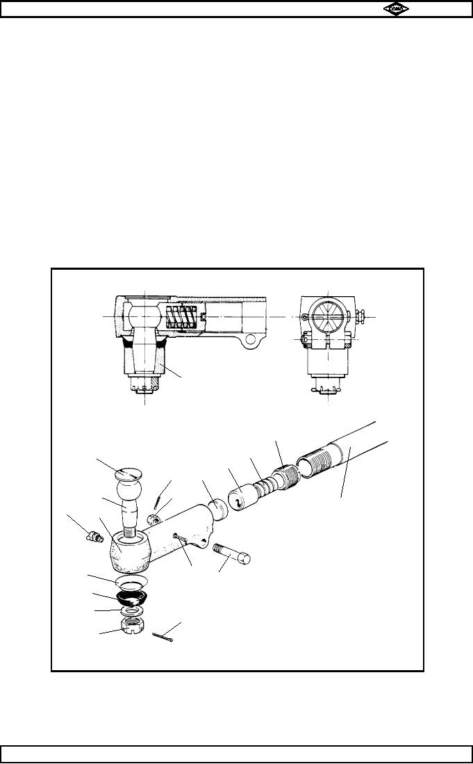
DISMANTLING BALL SOCKET SEE FIG No 16
14.1
Remove dirt seal (4) also dirt seal (pressing) (5) from ball pin.
14.2
Remove split pin (10) from pinch bolt nut (11).
14.3
Slacken pinch bolt nut (11) then unscrew and remove ball socket assembly from tie rod having first
marked ball socket body and tie rod to enable tracking on re-assembly.
14.4
Remove adjuster split pin (12) from ball socket body (7).
Using a suitable tool ie: a piece of 1 " x 1/8 " x 9 " flat bar, unscrew and remove adjusting piece (17).
14.5
Waggle ball (8) to free thrust cap (15).
Remove compression spring (16) also thrust cap (15) from ball socket body.
14.6
Using a hide faced mallet, tap ball pin (8) out of body. This operation will also remove cover plate (9)
from body (7).
14.7
The rubbing pad (14) can now be removed from body (7).
Thoroughly clean all parts and check for wear, renewing where necessary.
TP48
●
Steering lever
17
●
16
9
15
●
14
10
●
●
11
8
●
Tie rod
●
●
6
7
●
●
●
●
●
12
5
13
●
4
3
●
1
●
2
Fig No 16..
Spicer Speciality Axle Division
Page No.B15
Manual No. 1785 Issue A
J-45