
TM 5-2420-230-24-1
Spicer Speciality Axle Division - Technical Publications
SECTION 16
DISMANTLING OF DBM U.J. UNITS
Tooling and equipment required
a)
Light hydraulic / hand press.
b)
Punch (tool no.E557).
c)
Rest (tool no. E558).
d)
Metal ring (tool no.E559).
e)
Extractor & screw (tool no.E560).
f)
Copper hammer.
TP1000
7
7
6
1
4
2
2
3
5
4
3
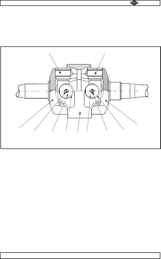
Fig. No.18
16.1
Remove lubricators (2) from opposite ends of cross trunnion (7) in central housing (5).
16.2
Using punch (tool no. E557) and copper hammer, knock bearing (3) inwards with light taps to release
pressure on circlip (snap ring)(4).
16.3
Remove circlip (snap ring) (4).
16.4
Repeat operations 16.2 & 16.3 for opposite end of trunnion (7).
16.5
Remove bearing using extractor tool (tool no. E560).
16.6
Remove axle shaft complete with trunnion (7) from central housing (5) by lightly twisting and pulling.
16.7
Remove circlips (4) from ends of trunnion (7) as stated in 16.2 to 16.4.
16.8
Position axle / trunnion assy. with free ends of trunnion (7) in position in rest (tool no. E558) under the
press.
16.9
Place metal ring (tool no. E559) over fork (1 or 6) and round bearing (3).
16.10
Gently remove bearing (3) using hydraulic / hand press.
16.11
Turn assembly over to remove bearing (3) from opposite side.
16.12
Repeat operations above to dismantle other drive shaft / U. J. assembly.
Spicer Speciality Axle Division
Page No.B17
Manual No. 1785 Issue A
J-47