
TM 5-2420-230-24-1
Spicer Speciality Axle Division - Technical Publications
SECTION 2
REMOVAL OF COMPLETE DRIVE HEAD ASSEMBLY
Note:- Part nos. marked (*) refer to drawing FH55
2.1
Disconnect air chamber pushrods from slack adjuster (91*) on both hub ends.Remove air chambers
from their brackets.
2.2
Remove planet carrier setscrews (66*) and washers (65*). Insert 2 off extractor bolts into planet carrier
and screw in to withdraw planet carrier evenly from hub (16*).
2.3
Remove sun gear circlip (62*) sun gear (61*) and spacer (60*) from end of U/J shaft (102*).
2.4
take out ball socket split pins (132 &138*) then unscrew and remove ball socket nuts (131 & 137*)
along with washer (90*).
2.5
Using a suitable extractor , remove ball socket assembly (122 & 124*)
from bottom steering levers (127 & 135*).
Note :- When separating ball socket from steering lever, an extractor tool MUST be used.
DO NOT strike areas around ball pin tapers with hammer blows under any
circumstances due to possible ball pin taper deformation.
2.6
Back off swivel top cap setscrews (80*) to release pressure in steering head . remove one of the
setscrews and replace with an eye bolt.
2.7
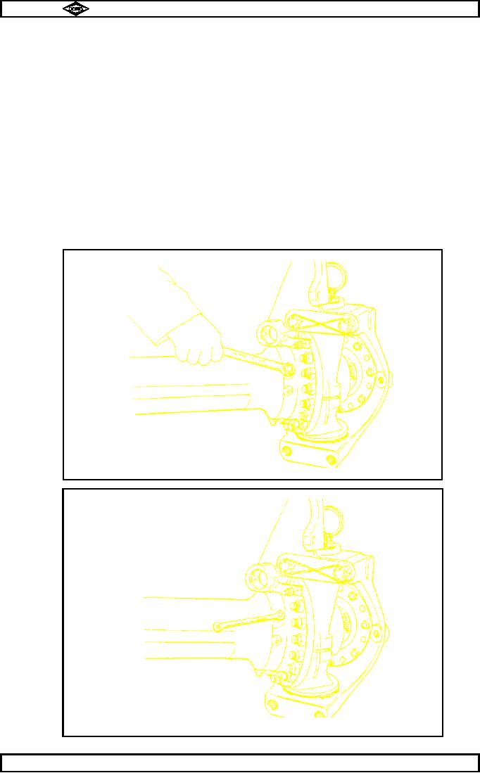
Unscrew and remove U.J. oil seal housing lockscrew nuts (115*) as shown in fig. no.1.
2.8
Unscrew and remove U.J. oil seal housing lockscrews (114*) as shown in fig. no.2.
TP44
Fig. No.1
TP45
Fig. No.2
Manual No. 1785 Issue A
Page No.C4
Spicer Speciality Axle Division
J-68