
TM 5-2420-230-24-1
Spicer Speciality Axle Division - Technical Publications
SECTION 16
SETTING THE SPIRAL BEVEL WHEEL (CROWNWHEEL) BEARINGS
16.1
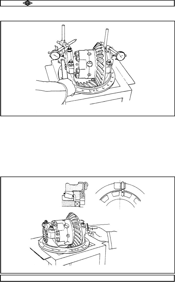
Set up two dial indicators diametrically opposite on bevel casing strap register points as shown in
fig. no. 12 and set each indicator to zero.
TP21
Fig No.12
16.2
Mark position of diff. bearing adjusting nuts (18 & 47) and then slacken each one slightly to ensure that
no spread is present. (ie. dial indicators remain at zero).
16.3
Re-tighten each diff. bearing nut (18 & 47) back to its marked position and then tighten a further notch
on each end to pre-load differential bearings (17 / 17A & 46 / 46A).
(a spring balance reading of 2 1/2 " lbs pull , ie. rolling resistance at o/d of diff. cage which equates to
8.75 lbs ins pre-load).
The sum of dial indicator readings should total between 0.002 " and 0.004 " (0.051 to 0.102mm).
The adjuster nut slots should line up with one of split pin holes in bevel casing straps (19).
16.4
Tighten strap nuts (21) to 128 - 142 lbs. ft. (174 - 193Nm.).
16.5
Fit diff. adjusting nut split pins (43) as shown in fig. no. 10.
16.6
Set up a dial indicator on spiral bevel wheel (crownwheel) (49) tooth and re-check that backlash is still
as previously set. (section 15. fig. no. 13).
TP75
Views showing position of split pin
Fit from underneath
Fig. No. 13
Manual No. 1785 Issue A
Page No.C16
Spicer Speciality Axle Division
J-80