
TM 5-2420-230-24-2
Balancer - Removal (0-59)
Section 0 - Engine Disassembly and Assembly - Group 00
Page 0-36
B Series Shop Manual
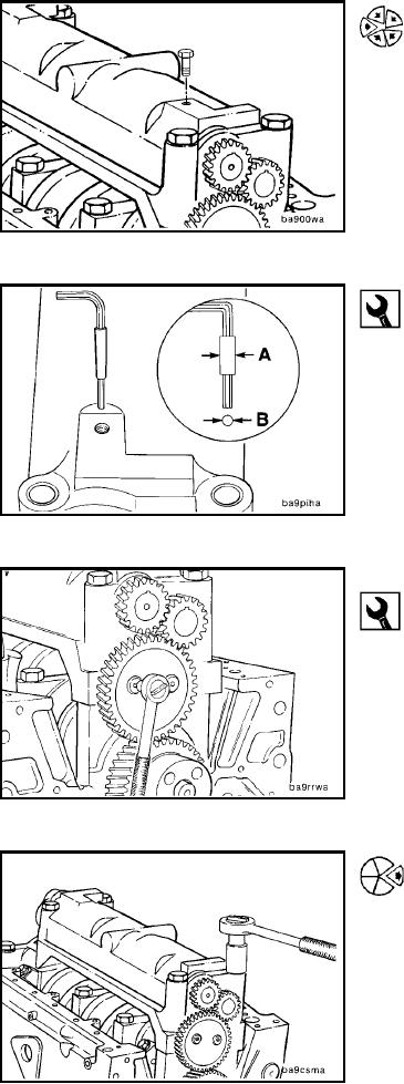
If the balancer shaft has a tapped hole, the shaft can be
locked in position by temporarily installing a M8 capscrew
through the housing and into the shaft.
4.5 mm Allen, 1 inch Wide Masking Tape
Follow this procedure if the shaft does not have a tapped
hole.
Wrap the 4.5mm allen wrench with masking tape until it
has a snug fit in the hole in the balancer housing.
A = Approximately 10mm [0.4 inch]
B = 10mm [0.4 inch]
Removing the Balancer (0-63)
8 mm Allen
Loosen the socket head capscrews for the balancer idler
gear retainer. DO NOT REMOVE THE CAPSCREWS.
Remove the No. 1 and No. 4 main bearing capscrews.
L-125