
TM 5-2420-230-24-2
Section 0 - Engine Disassembly and Assembly - Group 00
Crankshaft - Installation (0-71)
B Series Shop Manual
Page 0-45
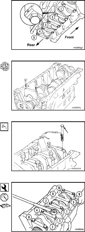
The main bearing caps are numbered for location. Num-
ber 1 starts with the front of the block, and the numbers
face the oil cooler side of the engine.
Position the main bearings and caps.
Lubricate the main bearing capscrew threads and un-
derside of the head with clean engine oil.
23 mm
Tighten the capscrews evenly following the illustrated
sequence.
NOTE: When the engine is equipped with a balancer the
main bearing caps cannot be torqued until the piston and rod
assemblies are installed. It is also necessary to establish Top
Dead Center before the balances can be installed. If a bal-
ancer is to be installed at a later procedure install and tighten
No. 2, 3, and 5 main bearing capscrews until the main
bearing caps are seated and proceed to procedure (0-72).
L-134