
TM 5-2420-230-24-2
Balancer - Installation (0-79)
Section 0 - Engine Disassembly and Assembly - Group 00
Page 0-62
B Series Shop Manual
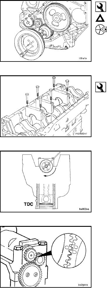
10 mm, 15 mm
Caution: Be sure timing pin is disengaged before rotat-
ing the engine.
Remove the crankshaft pulley and wire pointer.
Balancer - Installation (0-79)
23 mm
Rotate the cylinder block on the relaxed stand until the
crankshaft is positioned at the top and parallel to the floor.
The number 1 and number 4 main bearing capscrews
must be removed to install the balancer.
Rotate the crankshaft until No. 1 piston is at Top Dead
Center. The engine must have a cylinder at TDC for
correct gear teeth alignment when the balancer is
installed.
Rotate the balancer gears until the timing marks are
aligned. The balancer must be kept in this position for
correct installation on the engine.
L-151