TM 5-2420-230-24-2
Section 0 - Engine Disassembly and Assembly - Group 00
Balancer - Installation (0-79)
B Series Shop Manual
Page 0-63
13 mm
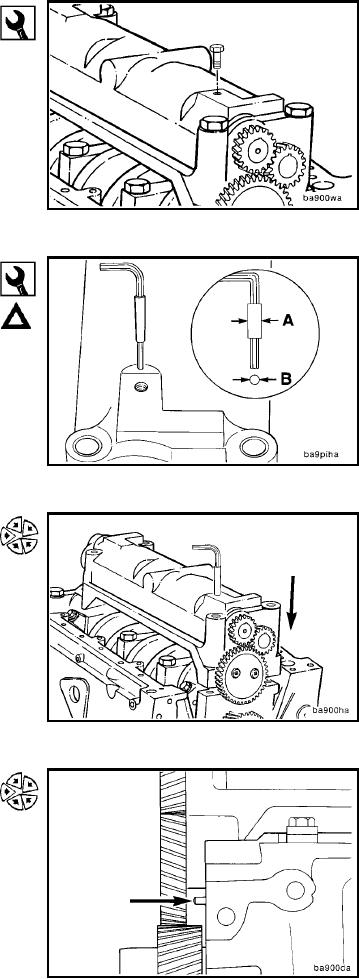
If the balancer shaft has a tapped hole, the shaft can be
locked in position by temporarily installing a M8 capscrew
through the housing and into the shaft.
4.5 mm Allen, 1 inch Wide Masking Tape
Caution: Make sure the idler gear retainer capscrews are
loose.
Follow this procedure if the shaft does not have a tapped
hole.
Wrap the 4.5mm allen wrench with masking tape until it
has a snug fit in the hole in the balancer housing.
A = Approximately 10mm [0.4 inch]
B = 10mm [0.4 inch]
Position the locked balancer assembly onto the main
bearing caps. The assembly must be located squarely
with the alignment ears against the side of the caps.
Align the slot in the idler gear retainer with the locating pin
in the main bearing cap. Slide the balancer into position.
L-152

