
TM 5-2420-230-24-2
Vibration Damper (001-052)
B3.9 and B5.9 Series Engines
Page 1-94
Section 1 - Cylinder Block - Group 01
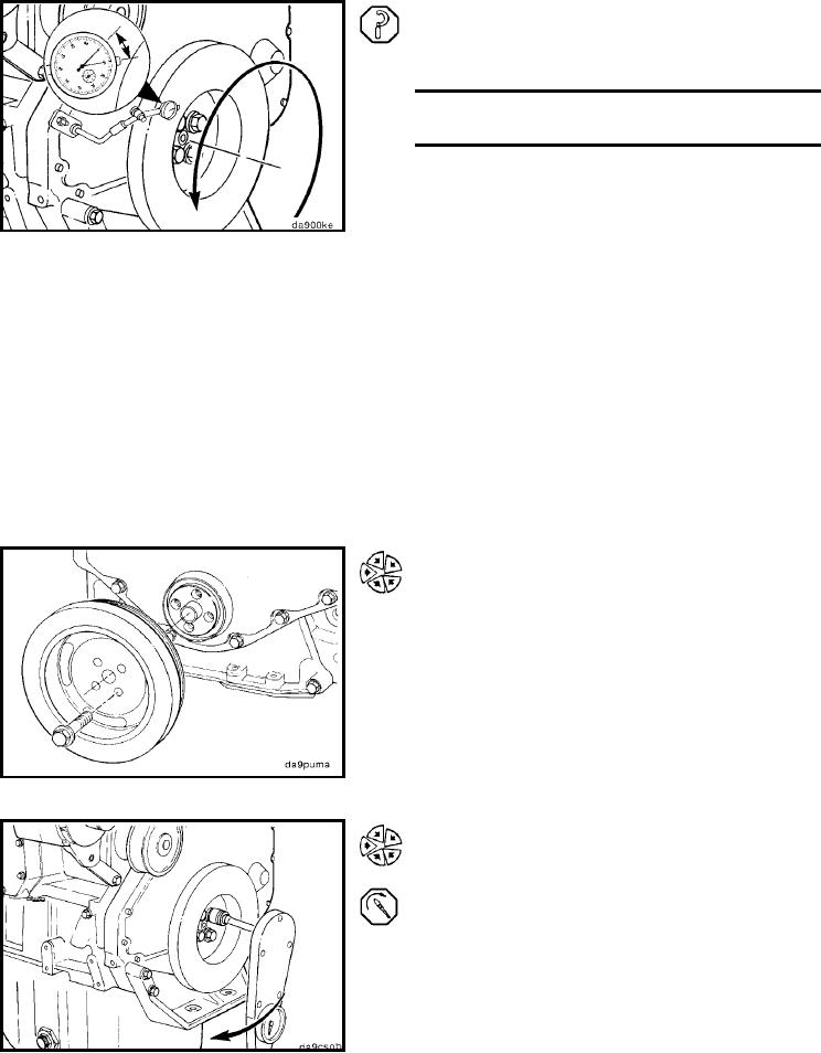
Rotate the crankshaft with engine barring tool, Part No.
3377371, 360 degrees, maintaining the position of the crank-
shaft.
Record the dial indicator movement.
Vibration Damper Wobbleper 25.4 mm [1.0 in] of
Radius
mm
in
0.18
MAX
0.007
Install (001-052-026)
NOTE: The B Series engines have two configurations for
the crankshaft pulleys and vibration dampers. Determine
which configuration is used and use the appropriate steps
in this procedure.
One Piece Pulley/Vibration Damper
Install the crankshaft vibration damper.
Install and tighten the crankshaft pulley/vibration damper
capscrews.
Torque Value: 125 Nm
[92 ft-lb]
Two-Piece Pulley/Vibration Damper
Install the vibration damper.
Install and tighten the vibration damper capscrews.
Torque Value: 200 Nm
[148 ft-lb]
Install the crankshaft pulley.
Install and tighten the crankshaft pulley capscrews.
Torque Value: 77 Nm
[57 ft-lb]
L-772