
TM 5-2420-230-24-2
Flywheel (016-005)
B3.9 and B5.9 Series Engines
Page 16-10
Section 16 - Mounting Adaptations - Group 16
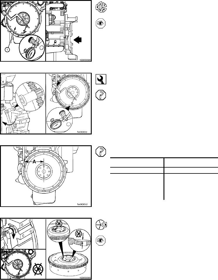
Flywheel Face Runout
Install the contact tip of the indicator against the flywheel
face, as close to the outside diameter as possible, to in-
spect the face (1) runout.
NOTE: Push the flywheel forward to remove the crankshaft
end clearance. Adjust the dial on the indicator until the
needle points to zero.
Barring Tool, Part No. 3824591
Use the barring tool, Part No. 3824591, to rotate the crank-
shaft one complete revolution. Measure the flywheel runout
at four equal points on the flywheel.
NOTE: The flywheel must be pushed toward the front of the
engine to remove the crankshaft end clearance each time
a point is measured.
The total indicator reading (TIR) must not exceed the fol-
lowing specifications:
Flywheel Radius (A)
Maximum of Flywheel
Face
mm
in
mm
in
203
8
0.203
0.008
254
10
0.254
0.010
305
12
0.305
0.012
356
14
0.356
0.014
406
16
0.406
0.016
If the flywheel face runout is not within specifications,
remove the flywheel. Check for nicks, burrs, or foreign
material between the flywheel mounting surface and the
crankshaft flange.
L-1338