
TM 5-2420-230-24-2
B3.9 and B5.9 Series Engines
Flywheel (016-005)
Section 16 - Mounting Adaptations - Group 16
Page 16-11
Install the clutch discs, pressure plate, transmission, and
driveline (if equipped) in reverse order of removal. Refer to
the manufacturer's instructions.
NOTE: Align the universal joints on each end of the
driveshaft to prevent vibration.
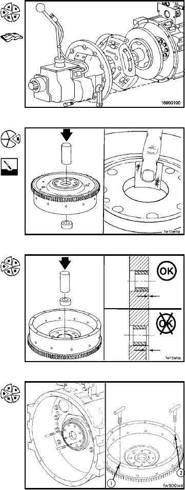
Install (016-005-026)
NOTE: Use a new pilot bearing when installing a new or
rebuilt clutch.
Use a mandrel and hammer to remove the pilot bearing.
Use a Scotch-BriteTM 7448, or equivalent, to clean the pilot
bore.
Use a mandrel and hammer to install the pilot bearing.
NOTE: The pilot bearing must be installed evenly with the
pilot bore surface.
Install two M12 x 1.25 x 90-mm guide pins into the crank-
shaft flange 180 degrees apart.
NOTE: If a clutch is used in the equipment, the threads in
the clutch pressure plate mounting capscrew holes can be
metric or standard. Be sure to use the correct capscrews.
Determine the capscrew thread design and size, and install
two t-handles into the flywheel (at points 1 and 2).
L-1339