TM 5-2420-230-24-2
Flywheel Housing (016-006)
B3.9 and B5.9 Series Engines
Page 16-16
Section 16 - Mounting Adaptations - Group 16
CAUTION
Do not force the crankshaft beyond the point where the
bearing clearance has been removed. Do not pry against
the flywheel housing. These actions could cause false
bearing clearance readings.
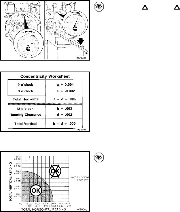
Rotate the crankshaft until the dial indicator is at the twelve
o'clock position and zero the gauge.
Using a pry bar, raise the rear of the crankshaft to its upper
limit. Record the value as (d) in the concentricity work
sheet. This is the vertical bearing clearance adjustment
and will always be positive.
Using the concentricity work sheet, determine the values
for the "total vertical" and "total horizontal" values.
The total horizontal is equal to the nine-o'clock reading (a),
minus the three-o'clock reading (c).
The total vertical is equal to the twelve-o'clock reading (b),
plus the bearing clearance (d).
Example:
Six o'clock = ref = 0
Nine o'clock = (a) = 0.004
Twelve o'clock = (b) = 0.003
Three o'clock = (c) = -0.002
Using the work sheet and the numbers from the example,
the total horizontal value equals 0.006 and the total vertical
value equals 0.005.
Mark the total horizontal value on the horizontal side of the
chart and the total vertical on the vertical side of the chart.
Using a straightedge, find the intersection point of the total
horizontal and total vertical values. The intersection point
must fall within the shaded area for the flywheel housing
concentricity to be within specification.
Using the total horizontal and total vertical values from the
previous example, the intersection point falls within the
shaded area. Therefore, the flywheel housing concentricity
is within specification.
L-1344

