
TM 5-2420-230-24-2
B3.9 and B5.9 Series Engines
Flywheel Housing (016-006)
Section 16 - Mounting Adaptations - Group 16
Page 16-15
Inspect for Reuse (016-006-007)
Inspect the flywheel housing for cracks, especially in the
bolt pattern area.
Inspect all surfaces for nicks, burrs, or cracks.
Use fine crocus cloth to remove small nicks and burrs.
Inspect for damaged threads commonly caused by cross-
threaded capscrews or installing an incorrect capscrew.
Helicoils are available to repair damaged threads.
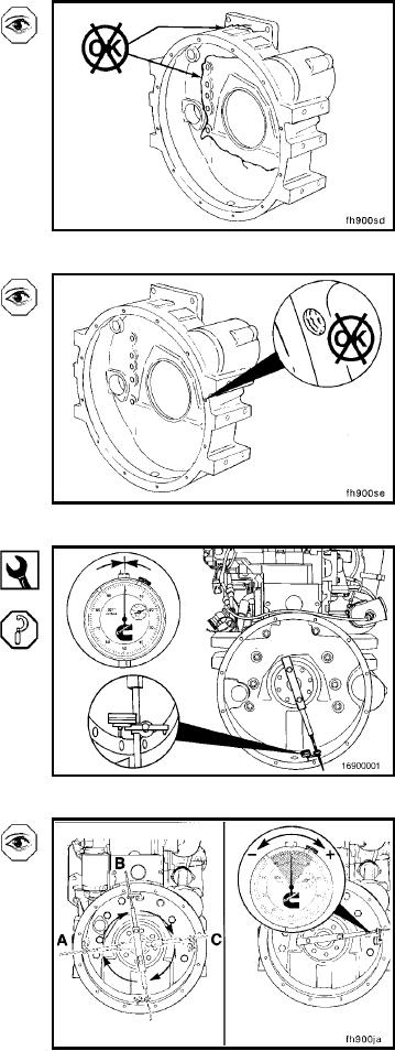
Measure (016-006-010)
Bore Alignment
Dial Indicator Gauge, Part No. 3376050
Attach the dial indicator gauge, Part No. 3376050, to the
crankshaft. The dial indicator can be mounted by any
method that holds the extension bar of the indicator rigid,
so it does not sag. If the bar sags or the indicator slips, the
readings obtained will not be accurate.
Position the indicator in the six-o'clock position, and zero
the gauge.
Slowly rotate the crankshaft. Record the readings obtained
at the nine-o'clock, twelve-o'clock, and three-o'clock po-
sitions as [a], [b], and [c] in the concentricity work sheet.
Recheck zero at the six-o'clock position.
The values for (a), (b), and (c) could be positive or negative.
Refer to the accompanying figure to determine the correct
sign when recording these values.
L-1343