
TM 5-2420-230-24-2
Flywheel Housing (016-006)
B3.9 and B5.9 Series Engines
Page 16-18
Section 16 - Mounting Adaptations - Group 16
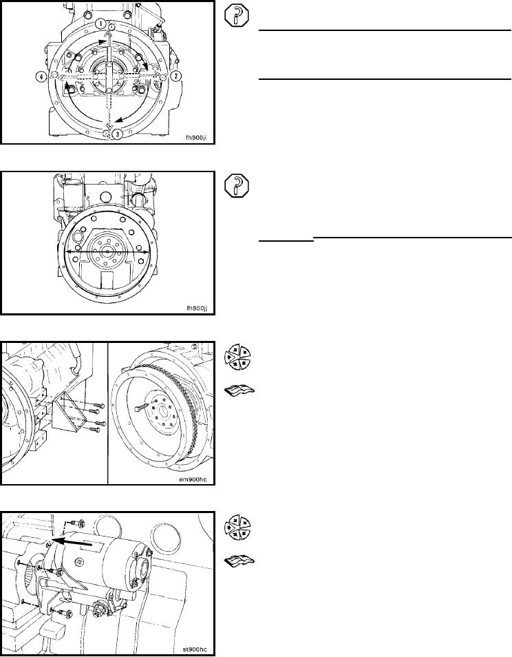
Determine the total indicator reading (TIR).
Example:
mm
in
12 o'clock
0.00
0.000
3 o'clock
+0.08
+0.003
6 o'clock
- 0.05
- 0.002
9 o'clock
+0.08
+0.003
Equals TIR
0.13
0.005
The maximum allowable total indicator reading (TIR) is
determined by the diameter of the housing bore. If out of
specifications, replace the housing.
SAE No.
Bore Diameter
TIR Max
mm
in
mm
in
2
447.68 to
17.625 to
0.20
0.008
447.80
17.30
3
409.58 to
16.125 to
0.20
0.008
409.70
16.130
Install (016-006-026)
Install both rear engine mounts.
Install the flywheel and clutch (if equipped). Refer to the
manufacturer's instructions.
Install the transmission and related components. Refer to
the manufacturer's instructions.
Install the starter motor. Refer to Procedure 013-020.
Connect the battery cables. Refer to Procedure 013-009.
L-1346