
TM 5-2420-230-24-2
B3.9 and B5.9 Series Engines
Flywheel Housing (016-006)
Section 16 - Mounting Adaptations - Group 16
Page 16-17
If the intersection point falls outside the shaded area, the
ring dowels must be removed and the housing reposi-
tioned.
NOTE: The ring dowels are not required to maintain con-
centricity of the housing; the clamping force of the
capscrews holds the housing in place.
After the ring dowels are discarded, install the flywheel
housing on the engine.
To position the housing, tighten the capscrews enough to
hold the flywheel housing in place, but loose enough to
allow small movement when struck lightly with a mallet.
Recheck the concentricity. When concentricity is within
specification, tighten the capscrews to the specified torque
value.
CAUTION
The dial indicator tip must not enter the capscrew holes,
or the gauge will be damaged.
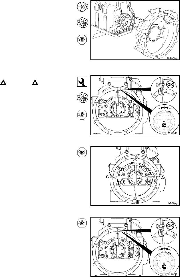
Face Alignment
Dial Indicator Gauge, Part No. 3376050
Install the dial indicator gauge, Part No. 3376050, as illus-
trated.
NOTE: The extension bar for the indicator must be rigid for
an accurate reading. It must not sag. Position the indicator
at the twelve-o'clock position. Adjust the dial until the needle
points to zero.
Slowly rotate the crankshaft. Record the readings at the
three-o'clock, six-o'clock, and nine-o'clock positions.
NOTE: The crankshaft must be pushed toward the front of
the engine to remove the crankshaft end clearance each
time a position is measured.
Continue to rotate the crankshaft until the indicator is at the
twelve-o'clock position. Check the indicator to make sure
the needle points to zero. If it does not, the readings will
be incorrect.
L-1345