
TM 5-2420-232-10
0041
SWEEPER CONTROLS
0041
WARNING
This machine is designed for use in normal outdoor atmospheric conditions. It should not be used
in an enclosed area without adequate ventilation. Do not use the machine in a potentially explosive
atmosphere, i.e., combustible vapors, gas, or dust. Failure to follow this warning may result in
injury or death to personnel.
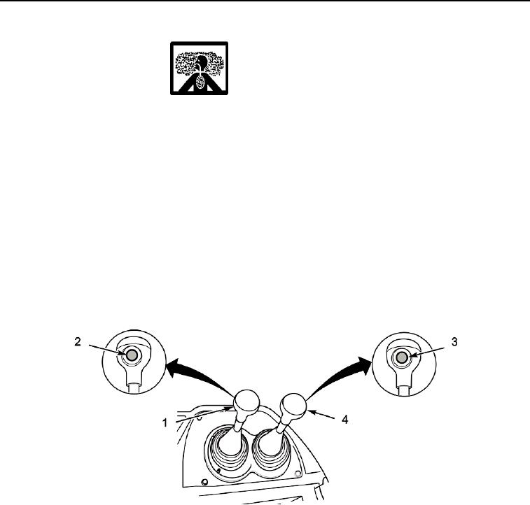
The sweeper is operated by a main control lever (Figure 1, Item 1) and an auxiliary control lever (Figure 1, Item 4). Pressing
the transmission dump pushbutton (Figure 1, Item 2) on the lever knob quickly disconnects the transmission from the engine.
This gives more power to the sweeper. The auxiliary solenoid button (Figure 1, Item 3) on the auxiliary control lever allows
the sweeper to be either operated or slewed. There is a second transmission kick-down button built into the main loader control
knob, for use when loading with the front bucket.
For individual sweeper movements (raise, lower, tilt forward, tilt back), the lever is moved in a "+" pattern.
Combined movements can be selected by moving the lever in directions between the four main ones. For example, the
sweeper is raised by pulling the lever straight back, while to tilt the sweeper back the lever must be moved to the left (e.g., if
you pull the lever diagonally back-and-left, the sweeper will both rise and tilt back).
The speed of sweeper actions depends on how far you move the lever. The further you move it, the faster the action. The lever
is spring-loaded to its central (hold) position. The sweeper will stay in any position until you move it.
435-A1400
Figure 1. Sweeper Controls
041
0041-2