
TM 5-3805-280-24-2
Cylinder Head and Valves
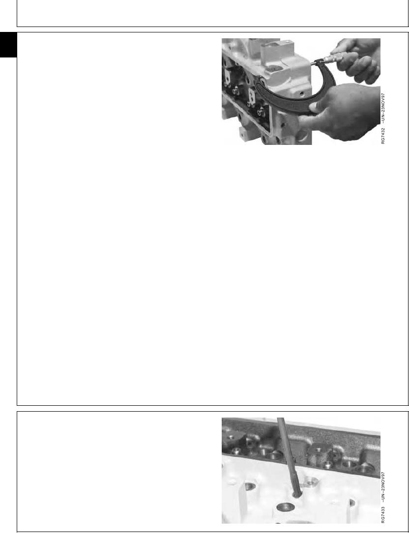
MEASURE CYLINDER HEAD THICKNESS
05
32
Measure head thickness from valve cover gasket
rail-to-combustion face.
If cylinder head thickness is less than minimum allowable
thickness, DO NOT attempt to resurface. Install a new
cylinder head.
When resurfacing cylinder head, remove ONLY what is
necessary to restore flatness.
Cylinder Head Thickness and Finish--Specification
New Cylinder Head Thickness .................................. 104.87--105.13 mm
(4.129--4.139 in.)
Minimum Acceptable Thickness............................. 104.24 mm (4.104 in.)
Combustion Face Surface Finish ............. 0.7--3.2 micrometers (31--125
(Surface Grind Only) (AA)
micro-in.)
Maximum Wave Depth .......................................... 0.012 mm (0.0005 in.)
Maximum Material Removal for ................................. 0.76 mm (0.030 in.)
Resurfacing
IMPORTANT: After resurfacing cylinder head, check
for flatness as described earlier. Also
check surface finish on combustion
face of head.
Measure and record valve recess in
cylinder head. (See CHECK VALVE
RECESS IN CYLINDER HEAD earlier in
this group.)
RG,05,DT7358 1911NOV971/1
CLEAN INJECTION NOZZLE BORES
IMPORTANT: Always turn the tool clockwise through
the bore, even when pulling back. This
will prevent premature wear on the tool.
Clean carbon deposits from nozzle bores with JDE39
Nozzle Bore Cleaning Tool. Blow debris from bore with
compressed air.
RG,05,DT7357 1911NOV971/1
13-90