
TM 5-3805-280-24-2
Cylinder Block, Liners, Pistons and Rods
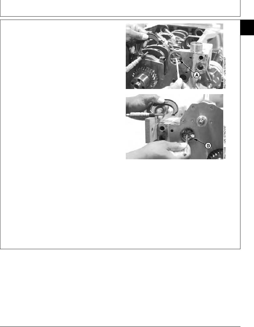
MEASURE BALANCER SHAFT BUSHING ID
10
45
IN BLOCK--4-CYLINDER ENGINES
1. Visually inspect and measure balancer shaft bushing
ID with bushing removed (A) and with bushing installed
(B).
If bushing is worn or not within specification, install
new bushings. (See REPLACE BALANCER SHAFT
BUSHINGS in Group 16.)
2. If necessary to replace bushing, remove bushing and
measure bore diameter in block.
If bore diameter in block is not within specification,
install a new cylinder block.
Balancer Shaft Bore in Block (Bushing Removed)--Specification
ID ............................................................................... 43.262--43.288 mm
(1.7032--1.7042 in.)
Balancer Shaft Bushing--Specification
ID ............................................................................... 40.177--40.237 mm
(1.5818--1.5841 in.)
Balancer Shaft Journal-to-Bushing--Specification
A--Bore Without Bushing
B--Bore With Bushing
Clearance ...................................................................... 0.016--0.102 mm
(0.0006--0.0040 in.)
RG,10,DT7398 1911NOV971/1
13-158