
TM 5-3805-280-24-2
Cylinder Block, Liners, Pistons and Rods
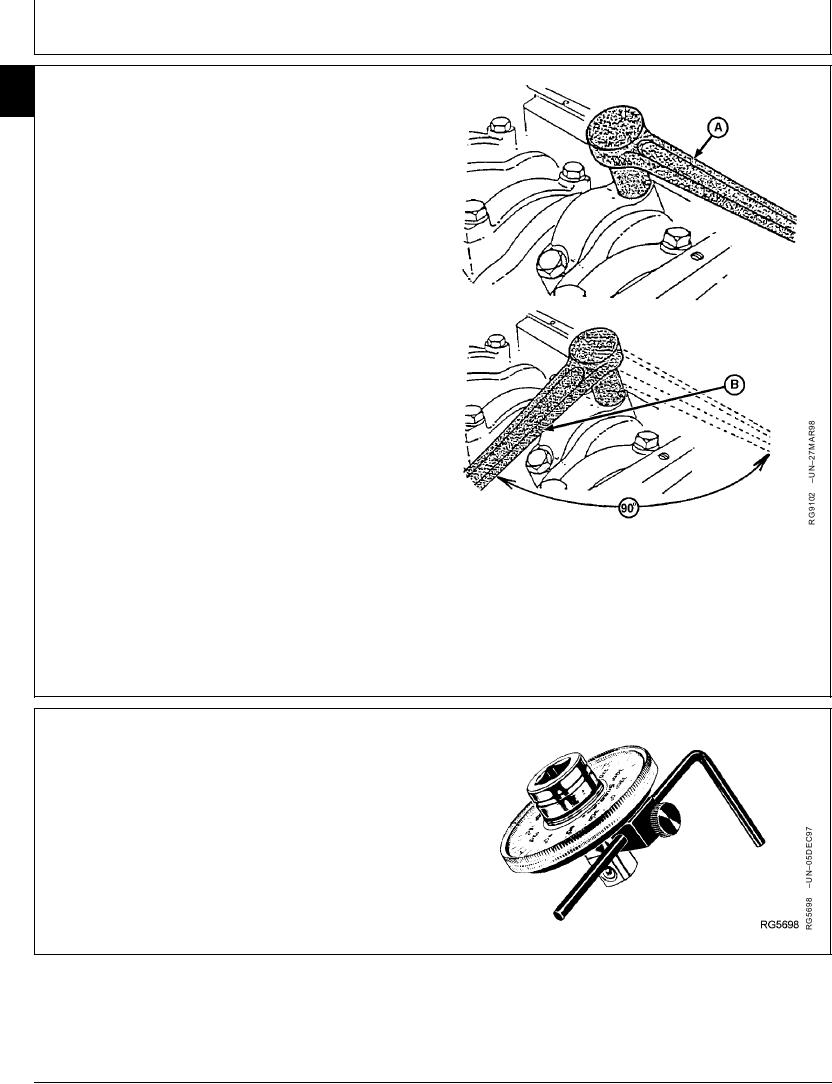
TORQUE-TURN CONNECTING ROD CAP
10
62
SCREWS
USING ENGINE AXIS METHOD TO TORQUE-TURN
CONNECTING ROD CAP SCREWS
1. After tightening cap screws to initial torque values,
mark connecting rod cap and socket.
2. Position handle of wrench parallel to centerline of
engine crankshaft axis (A).
3. Tighten 1/4 turn (90--100) clockwise until handle of
wrench is perpendicular to centerline of engine
crankshaft axis (B) as shown.
Connecting Rod Cap Screws--Specification
Torque Turn.............................................. 1/4 Turn (90--100) After Initial
Torque
A--Parallel to Centerline Crankshaft
B--Perpendicular to Centerline Crankshaft
RG,10,DT7386 1911NOV971/2
USING JT05993 TORQUE ANGLE GAUGE TO
TORQUE-TURN CONNECTING ROD CAP SCREWS
After tightening cap screws to initial torque values
provided earlier, follow directions provided with JT05993
Gauge and TORQUE-TURN each cap screw 90--100.
RG,10,DT7386 1911NOV972/2
13-175