
TM 5-3805-280-24-2
Camshaft, Balancer Shafts and Timing Gear Train
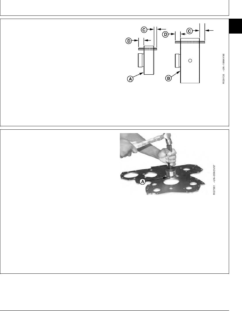
INSTALL IDLER SHAFT SPRING PINS (IF
16
45
EQUIPPED)
Install spring pins in lower (A) and upper (B) idler gear
shaft. This locks thrust washer to shaft to allow 4.32 mm
(0.170 in.) (C) projection above front face of each shaft.
The pins on idler shafts extend through both rear and
front thrust washers.
Lower and Upper Idler Shaft Spring Pin Protrusion
(D)--Specification
Protrusion ................................................ 2.79--4.83 mm (0.11--0.19 in.)
A--Lower Idler Gear Shaft
B--Upper Idler Gear Shaft
C--4.32 mm (0.170 in.) Projection
D--2.79--4.83 mm (0.11--0.19 in.) Protrusion
RG,16,DT7479 1914NOV971/1
INSTALL UPPER IDLER SHAFT IN FRONT
PLATE
IMPORTANT: Oil holes in idler shaft must be properly
indexed to provide adequate lubrication
to idler gear bushing.
1. Install thrust washer (A) and upper idler shaft into front
plate. Spring pin (if equipped) must extend through
hole in thrust washer and front plate.
IMPORTANT: Install thrust washer (A) with "X" mark
facing away from gear (toward plate).
A--Thrust Washer
2. Drive or press shaft into front plate until thrust washer
is fully seated.
RG,16,DT7478 1914NOV971/1
13-277