
TM 5-3805-280-24-2
Camshaft, Balancer Shafts and Timing Gear Train
16
4. Later engines1 have balancer shafts with removable
49
weights. Install weights to balancer shafts using new
cap screws and nuts. Tighten to specifications.
Balancer Shaft Removable Weights--Specification
Torque ............................................................................. 58 Nm (43 lb-ft)
1
Serial Numbers: Dubuque-built engines (700877-- ), Saran-built
engines (500212-- ), Torreon-built engines (001000-- ).
RG,16,DT7475 1914NOV973/7
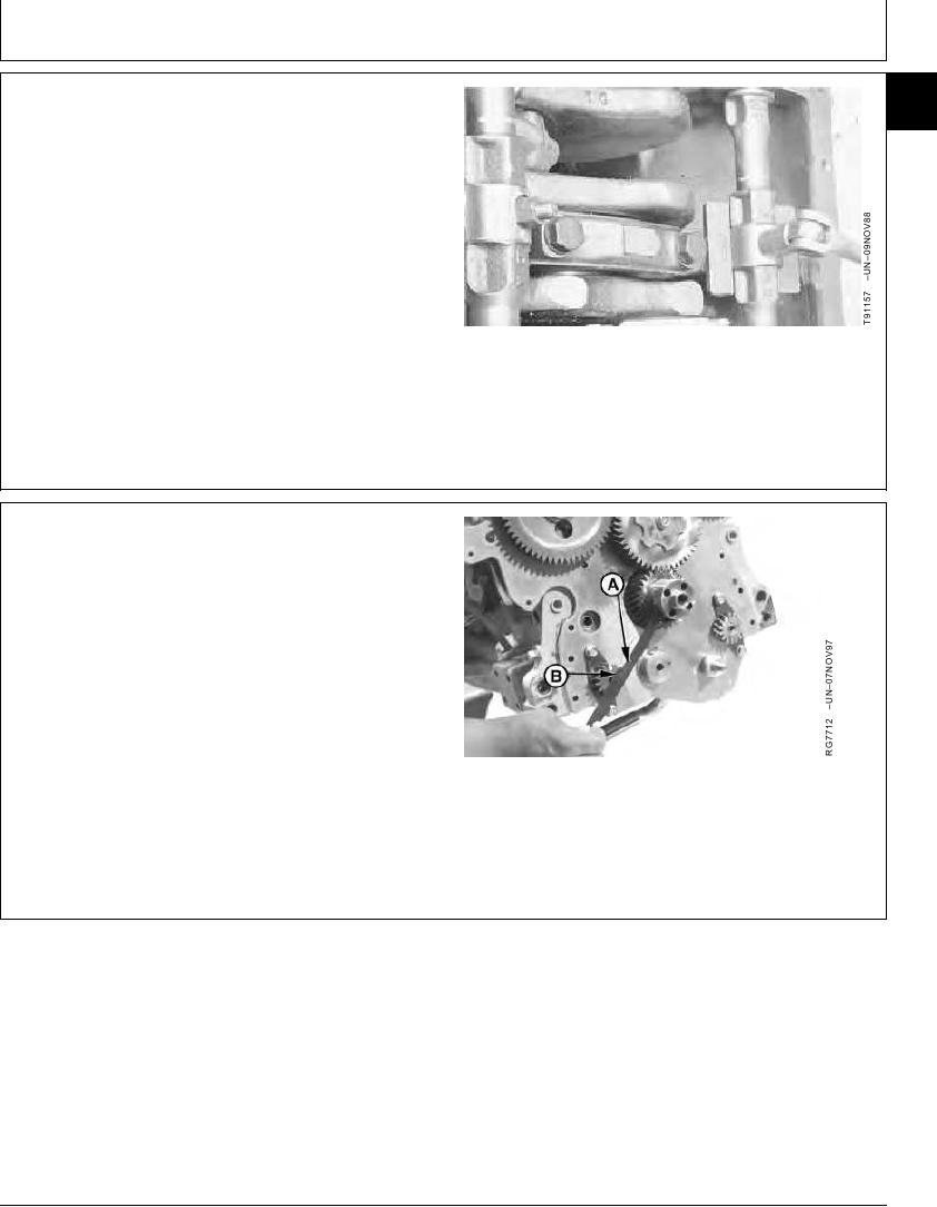
5. Turn right (camshaft side) balancer shaft so timing
mark on gear is aligned with JD254A Timing Tool (A).
Timing mark on balancer shaft gear must point to
centerline of crankshaft when correctly timed.
NOTE: Keyway (B) in balancer shaft gear will be at 12
O'clock position, when engine is locked at No. 1
TDC compression.
6. Apply TY6333 High-Temperature Grease to idler gear
bushing ID and shaft OD. Install lower idler gear
without turning balancer shaft.
A--Timing Tool
B--Keyway
Continued on next page
RG,16,DT7475 1914NOV974/7
13-281