
TM 5-3805-280-24-2
Camshaft, Balancer Shafts and Timing Gear Train
16
IMPORTANT: Use the timing mark corresponding to
54
the number of cylinders the engine has
that is being timed.
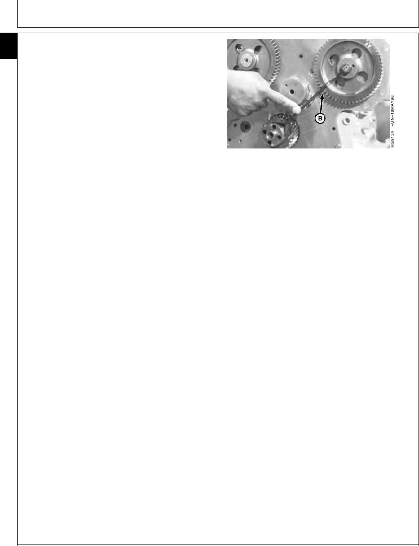
10. Check injection pump gear timing with JD254A Timing
Tool resting on nose of crankshaft and center of
injection pump shaft. Timing mark (B) on injection
pump drive gear, as described in table below, must
align with timing tool (as shown).
INJECTION PUMP GEAR TIMING MARKS
Injection Pump Model
Timing Mark
4-Cylinder Engine:
Stanadyne DB2 ......................................................
SD2 4
B--Timing Mark
Stanadyne DB4 ......................................................
SD4 4
Lucas DP201 and DP203 ......................................
L4
6-Cylinder Engine:
Stanadyne DB4 ......................................................
S6
Lucas DP201 and DP203 ......................................
L6
Lucas (Early 1170 Combines) ................................
L6
Lucas (Late 1170 Combines) .................................
6C or 6Z
IMPORTANT: To ensure proper lubrication of new
upper idler gear bushing and camshaft
bushing, install new upper idler gear
with the reference number facing away
from engine.
11. Lubricate upper idler gear bushing ID and shaft OD
with TY6333 High-Temperature Grease. Using
JDG791A Idler Gear Installer Pilot1, install idler gear
without turning camshaft gear or injection pump gear.
NOTE: Install thrust washer with "X" mark facing away
from gear.
12. Lubricate upper idler gear cap screw threads with oil.
Install upper idler gear thrust washer and cap screw.
Tighten cap screw to specifications.
Upper Idler Gear Cap Screw--Specification
Torque ............................................................................. 70 Nm (53 lb-ft)
1
JDG791A needs to be modified to allow space for the spring pin in idler
shaft.
Continued on next page
RG,16,DT7474 1914NOV974/5
13-286