TM 5-3805-280-24-2
Camshaft, Balancer Shafts and Timing Gear Train
INSTALL AND TIME CAMSHAFT AND
16
52
ROTARY FUEL INJECTION PUMP
1. Using JDG820 or JDE83 Flywheel Turning Tool and
JDE81-4 Timing Pin, lock No. 1 piston at TDC
2. Install fuel injection pump on front plate.
3. Install fuel injection pump drive gear and new retaining
nut. Time injection pump to engine. (See Group 35 for
injection pump timing.)
4. Tighten injection pump-to-front plate hex nuts to
specifications.
Injection Pump-to-Front Plate Nuts--Specification
Torque ............................................................................ 27 Nm (20 lb-ft).
5. Tighten injection pump drive gear retaining nut to
specifications listed below:
Stanadyne: Model DB2--Specification
Torque ........................................................................... 125 Nm (92 lb-ft)
Stanadyne: Model DB4--Specification
Torque ......................................................................... 195 Nm (144 lb-ft)
Lucas: Model DP201 and DP203--Specification
Torque ............................................................................. 81 Nm (60 lb-ft)
6. Lubricate camshaft bearing journals, lobes, and
followers with TY6333 High-Temperature Grease.
IMPORTANT: DO NOT allow camshaft lobes to drag
on camshaft bore or bushing surfaces
while installing camshaft. Bearing
surfaces may become scratched or
scored. Rotate camshaft during
installation to avoid obstruction in any
bore.
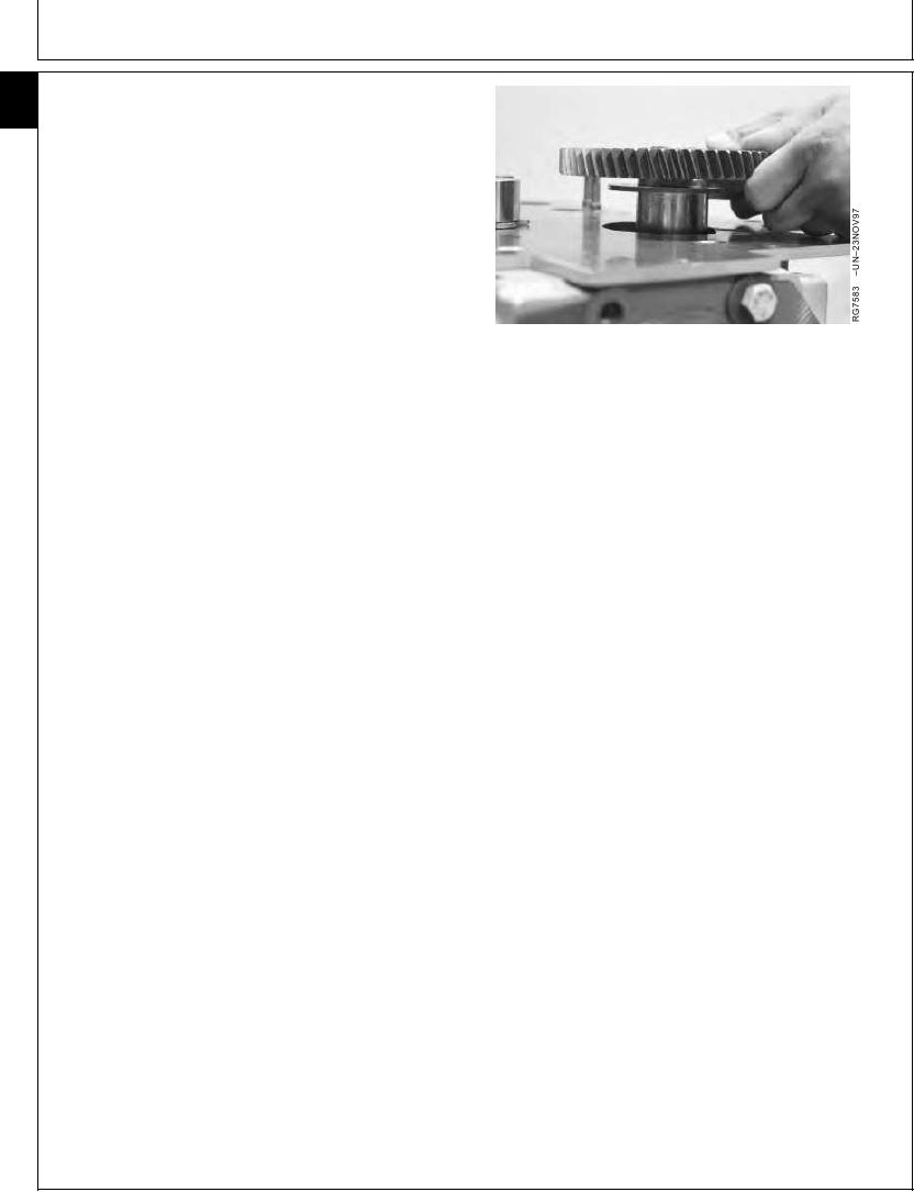
7. Install camshaft and thrust plate in cylinder block. Be
careful not to damage bushing ID.
Continued on next page
RG,16,DT7474 1914NOV971/5
13-284

