TM 5-3805-280-24-2
Lubrication System
20
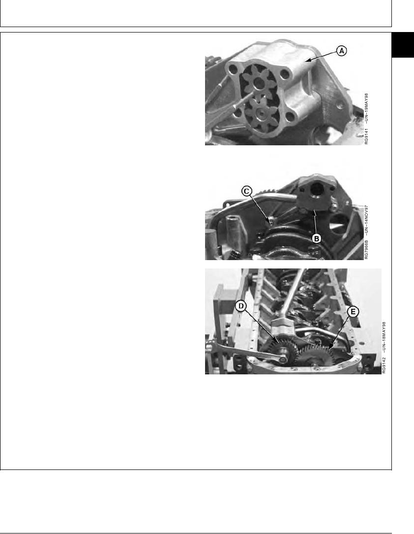
3. Lubricate lower idler gear cap screw threads (C) and
27
draw into leg of housing finger tight while installing oil
pump housing with gears (A) onto front plate.
4. Wedge a hardened round punch between the drive
gear and idler gear.
5. Install oil pump drive gear (D) so that it meshes with
lower idler gear (E) and balancer shaft gear (4045
engines only) without altering gear train timing.
6. Install new retaining nut and tighten to specifications.
Oil Pump Drive Gear "Staked" Nut--Specification
Torque ............................................................................. 50 Nm (37 lb-ft)
7. Stake oil pump drive gear nut by applying three center
punch marks near ID of shaft.
8. Swing (position) oil pump cover (B) onto pump housing
and install two lower cap screws finger tight.
A--Oil Pump Housing
B--Oil Pump Cover
C--Idler Gear Cap Screw
D--Oil Pump Drive Gear
E--Lower Idler Gear
Continued on next page
RG,20,DT7520 1917NOV972/4
13-320

