
TM 5-3805-280-24-2
Cooling System
25
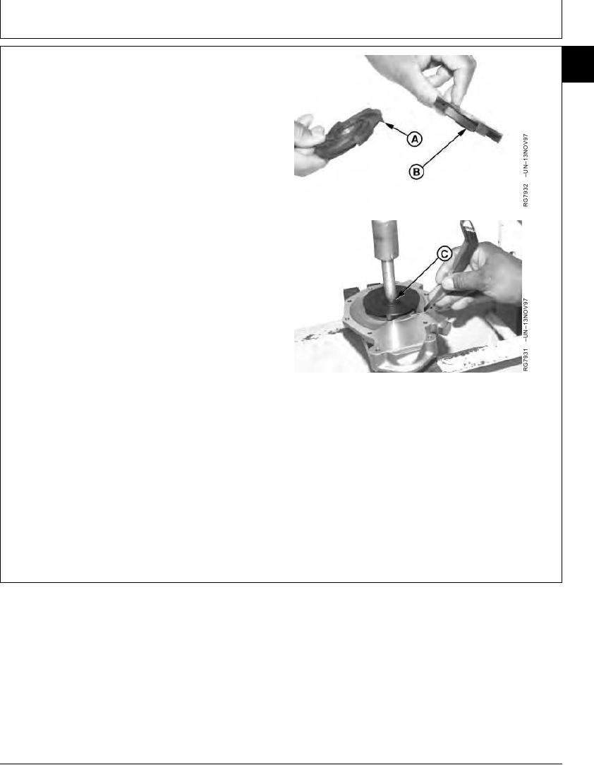
NOTE: Water pumps are available with two different
17
types of impellers to assure adequate coolant flow
for a given engine application. Standard flow
pumps have fins on both sides of impeller (A).
High flow pumps have fins on one side of impeller
(B). Be sure to replace impeller with the same
type of impeller to assure proper engine cooling.
7. Support front nose of water pump shaft.
IMPORTANT: When installing impeller, press only on
brass bushing (C) as impeller could
crack.
8. Using an appropriate driver, install impeller onto shaft
to the specified dimension below.
Water Pump Impeller (Standard Flow)--Specification
Position ................................................ 2.46--2.58 mm (0.096--0.102 in.)
below end of shaft
Water Pump Impeller (High Flow)--Specification
Position ................................................... Flush 0.13 mm (0.005 in.) with
end of shaft
Water Pump Housing-to-Impeller--Specification
A--Standard Flow Impeller
B--High Flow Impeller
Minimum Clearance.................................................... 0.27 mm (0.010 in.)
C--Bushing
9. Rotate impeller a complete revolution by hand and
check with feeler gauge for impeller-to-housing
clearance.
10. Install new foam filters in weep holes.
RG,25,JW7554
1920NOV972/2
13-340