
TM 5-3805-280-24-2
Cooling System
25
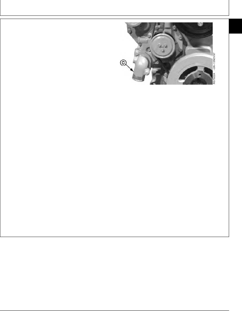
3. Using a new O-ring, install water pump inlet elbow (C),
19
if removed. Tighten cap screws to specifications.
Water Pump Inlet Elbow--Specification
Torque ............................................................................. 35 Nm (26 lb-ft)
4. Install poly-vee belts. Be sure that belt is correctly
seated in all pulley grooves.
5. Install fan and tighten cap screws with lock washers to
the following specification:
Fan-to-Pulley Hub M8 Cap Screws--Specification
C--Inlet Elbow
Torque ............................................................................. 35 Nm (26 lb-ft)
Fan-to-Pulley Hub M10 Cap Screws--Specification
Torque ............................................................................. 70 Nm (52 lb-ft)
6. Fill cooling system with proper coolant. (See Fuels,
Lubricants, and Coolant--Group 02.)
IMPORTANT: Air must be expelled from cooling
system when refilled. Loosen
temperature sending unit fitting at rear
of cylinder head or plug in thermostat
housing to allow air to escape when
filling system. Tighten fitting or plug
when all the air has been expelled.
RG,25,JW7553
1920NOV972/2
13-342