
TM 5-3805-280-24-2
Fuel System Operation and Tests
HOW THE ANEROID WORKS (IF EQUIPPED)
115
76
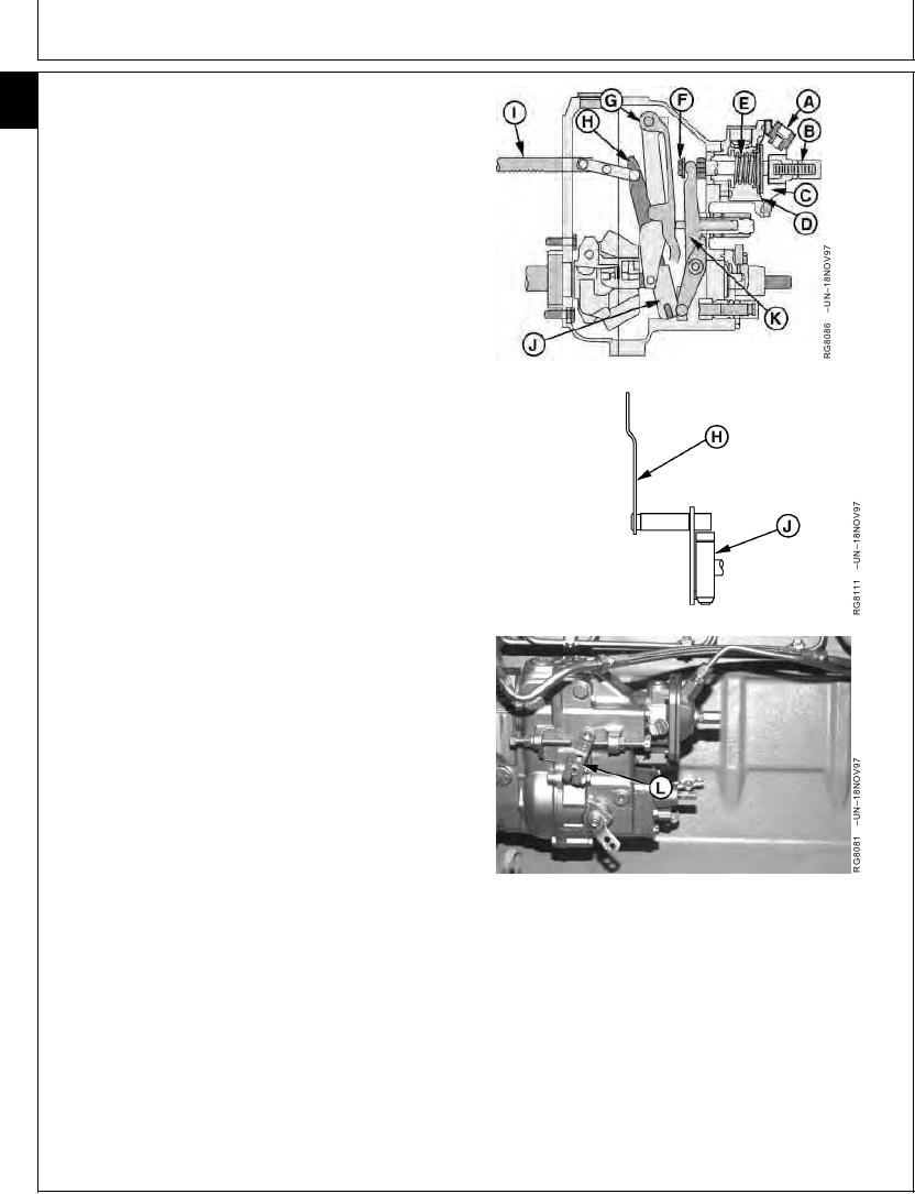
NOTE: In-line injection pump shown. Operation of aneroid
on rotary pumps is similar in theory.
Intake manifold pressure (created by the turbocharger)
enters aneroid at (A). It is directed to upper side of
diaphragm chamber (C) and exerts pressure on
diaphragm (D).
When the pressure rises to about 100 kPa (1 bar) (15
psi), or about 1000 engine rpm under moderate to heavy
loads, spring (E) pressure is overcome. Diaphragm then
moves aneroid control shaft (F) downward.
Control lever (H) has "two" legs. The inner leg connects
with control block (J) and the aneroid control lever (K) and
bears on the flat surface of aneroid control shaft. The
outer leg bears against a block riveted to the control rack
(I).
NOTE: Diaphragm adjusting screw (B) regulates the
minimum fuel delivery quantity at a specified rpm
and zero pressure acting on the diaphragm. The
diaphragm spring determines acceleration time
(the greater the spring tension, the greater the
manifold pressure required to overcome spring
tension; hence, a slower acceleration).
Downward movement of the throttle lever (L) causes arm
to rotate on fuel control shaft, permitting control rack to
move its normal amount.
In the intake manifold pressure is below 100 kPa (1 bar)
(15 psi) because of low engine speed, or is under light
load at higher engine speeds, the aneroid spring pressure
is greater than the intake manifold pressure. As a result,
the control rack travel is limited (therefore, fuel delivery is
limited) by the arm and adjusting shaft.
Aneroid control will be in effect until the manifold pressure
A--Intake Manifold Pressure Line Connection
is high enough to overcome diaphragm spring pressure.
B--Diaphragm Adjusting Screw
C--Diaphragm Chamber
D--Diaphragm
E--Spring
F--Aneroid Control Shaft
G--Guide Lever
H--Control Lever
I--Control Rack
J--Control Block
K--Aneroid Control Lever
L--Throttle Lever
RG,115,JW7683
1924NOV971/1
13-603