TM 5-3805-280-24-2
Fuel System Operation and Tests
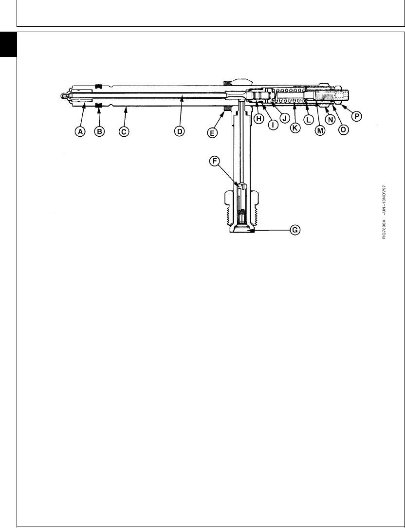
FUEL INJECTION NOZZLES--GENERAL INFORMATION AND OPERATION
115
78
A--Nozzle Tip
F--Edge-Type Filter
K--Valve Spring
O--Pressure Adjusting
B--Carbon Stop Seal
G--Fuel Inlet
L--Spring Washer
Screw
C--Nozzle Body
H--Upper Guide
M--Lift Adjusting Screw
P--Lock Nut
D--Nozzle Valve
I--Upper Seal
N--Lock Nut
E--Upper Seal Washer
J--Spring Seat
A leak-off line tee is attached to the upper end of the
The injection nozzles are located in the engine cylinder
injection nozzle, secured by a grommet and hex nut.
head and are of the spring and valve type,
hydraulically operated by fuel delivered from the
Metered fuel, under high pressure, is delivered by the
injection pump.
injection pump through the nozzle inlet (G) on the
valve body into the area surrounding the valve. When
A locating clamp positions the nozzle assembly in the
fuel pressure reaches nozzle opening pressure, the
cylinder head. The nozzle is sealed at the top end by a
valve is forced from its seat against the pressure of the
seal washer (E). A carbon stop seal (B), located on the
spring, permitting a measured amount of fuel to enter
lower end of the nozzle body (C), prevents carbon
the combustion chamber through four small holes in
from collecting around the nozzle in the cylinder head.
the nozzle tip.
Enclosed in the nozzle body are the valve (D), valve
After fuel has been injected, the spring closes the
spring (K), and spring seat (J). The nozzle operating
valve. In actual operation, the valve opens and closes
pressure is controlled by the pressure adjusting screw
very rapidly, providing a distinct chatter.
(O) in the upper end of the nozzle body. Valve lift is
adjusted by the lift adjusting screw (M) located in the
pressure adjusting screw. The nozzle tip (A) is pressed
into the nozzle body and cannot be separated.
Continued on next page
RG,115,JW7681
1924NOV971/2
13-605

