TM 5-3805-280-24-2
Speed Controls
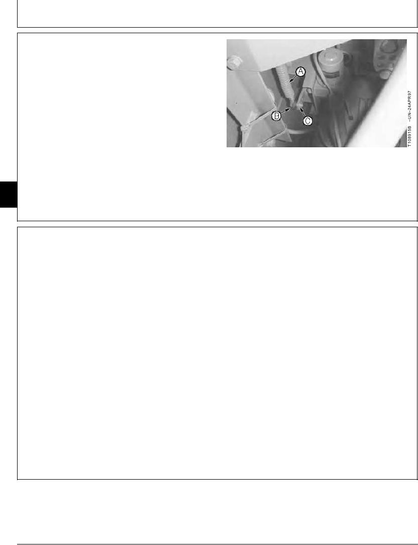
2. Install ball joint (B) in the OUTER hole of arm (C).
3. Adjust arm on control motor shaft or speed control
cable (A) in bracket so cable is vertical.
4. Do Engine Control Motor and Sensor Adjustment and
then the Engine Speed Learning Procedure. (See
procedures in this group.)
A--Speed Control Cable
B--Ball Joint
C--Outer Hole of Arm
05
0515
8
TX,05,UU3888
1918SEP982/2
ENGINE CONTROL MOTOR AND SENSOR
ADJUSTMENT
When the following components are repaired or replaced,
or when engine speeds deviate from specification, the
engine control motor adjustment and engine speed
learning procedure must be performed.
Engine
Engine speed control cable
Engine control motor and sensor
Engine and pump controller
Fast and slow idle stop screws
1. Compare the fast and slow idle stop screws on the
injection pump to speed specification. (See Injection
Pump Fast and Slow Idle Stops Adjustment in this
group.)
2. Turn key switch to ON.
3. Turn the engine rpm dial to slow idle.
Continued on next page
TX,05,UU3889
1918SEP981/2
14-19

