
TM 5-3805-281-24-1
System Information
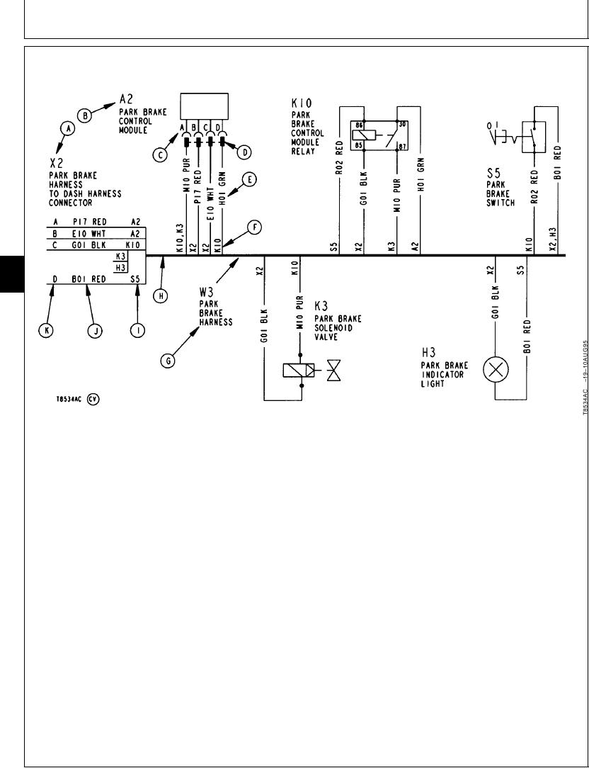
READING A WIRING DIAGRAM
9015
05
22
A--Harness Connector
E--Wire Number And/Or
H--Wiring Harness
Letter/Number
Color
I--Component(s)
Identification
F--Component(s)
Identification
B--Component
Identification
Number/Letter Wire Is
Letter/Number
Number/Letter Wire Is
Routed To
Identification
Routed To
J--Wire Number And/Or
C--Component Connector
G--Harness Identification
Color
Pin Number Or Letter
Letter/Number And
K--Harness Connector Pin
D--Component Connector
Description
Number Or Letter
designation and description used in the System
Each harness on the machine is drawn showing
Functional Schematic. Components with integral
components, connectors, and wires. Harnesses (G)
connectors (D) have pin number/letters indicated (C).
are identified by a letter/number designation and
Wires from harness to components are identified by
description (W3 PARK BRAKE HARNESS, Etc.).
letter/number designation (E). Component identification
letter/number (F) indicates component wire is routed
Each component (B) is represented by a schematic
to.
symbol and is identified by the same letter/number
Continued on next page
CED,OUTX466,1363 1915OCT981/2