
TM 5-3805-281-24-2
Removal and Installation
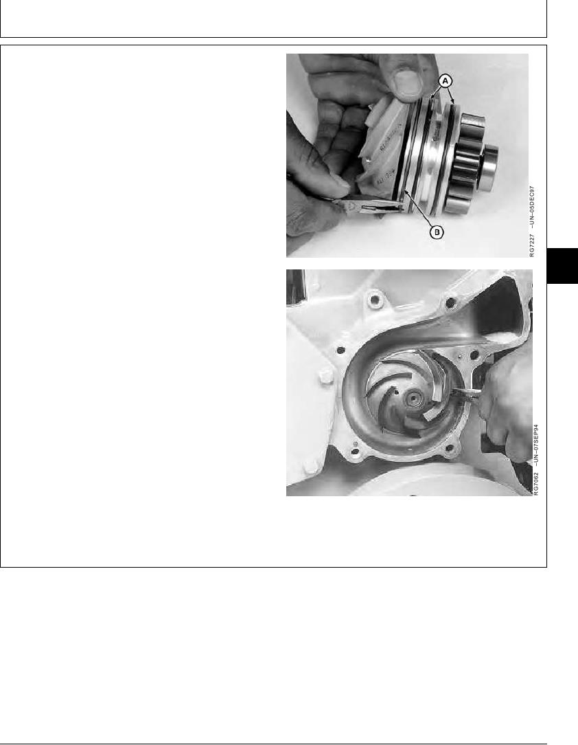
2. Install new O-rings (A) in rear grooves of water pump
housing and apply a light coat of clean engine oil to
O-rings.
3. Install a new retaining ring (B) in front (smallest)
groove of water pump housing and compress both
ends of retaining ring together with a small needle
nose plier.
NOTE: Retaining ring ends should be at 3 o'clock position
and water pump weep hole should align with hole
in timing gear cover when installing water pump
assembly.
4. Compress retaining ring ends and install water pump
assembly into pilot bore of timing gear cover. Make
04
sure that pump drive gear properly meshes with
0400
crankshaft gear.
23
5. Release retaining ring ends and verify that retaining
ring is firmly seated in groove of timing gear cover.
6. Install water pump cover with bypass tube using a new
gasket. Tighten all 3/8-in. cap screws and all 5/16 in.
cap screws.
Water Pump Cap Screw (3/8-in.)--Specification
Torque ............................................................................ 47 Nm (35 lb-ft)
Water Pump Cap Screw (5/16-in.)--Specification
Torque ............................................................................. 27 Nm (20 lb-ft)
A--O-Ring (2 used)
B--Retaining Ring
Continued on next page
CED,OUOE024,205
1914MAY982/3
11-23