
TM 5-3805-281-24-2
Crankshaft, Main Bearings, and Flywheel
REPLACE (CRANKSHAFT) OIL PUMP DRIVE
GEAR
IMPORTANT: Protect all machined surfaces of
crankshaft from grinding debris and
weld spatter when removing old gear
and installing new gear. DO NOT use a
cutting torch to remove failed gear.
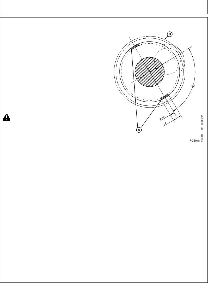
1. Using a rotary grinding wheel or parting disc, grind
weld beads (A) until flush with crankshaft flange.
2. Remove gear (B) by alternately striking gear at each
weld location using a brass drift and soft lead mallet.
3. After removal of gear, clean up O.D. of crankshaft
flange and remove any burrs or remaining weld bead
to eliminate interference when installing new gear.
CAUTION: Oil fumes or oil can ignite above
193C (380F). Use a thermometer and do not
exceed 182C (360F). Do not allow a heating
element to be in direct contact with the oil. Heat
the oil in a well-ventilated area. Plan a safe
handling procedure to avoid burns.
Removing Crankshaft Oil Pump Drive Gear
IMPORTANT: DO NOT OVERHEAT GEAR. SEE
CAUTION. Overheating may also
destroy original heat treatment of gear.
4. Heat crankshaft gear to 148C (300F) using either
heated oil or oven heat.
5. Drive gear onto crankshaft flange until flush against
shoulder.
NOTE: When driving oil pump onto crankshaft flange, the
beveled edge of gear teeth should face the
flywheel end of crankshaft.
6. Weld two 25.4 mm (1 in.) beads according to
illustration using 1/8 in. diameter 7018 welding rod.
Grind away excess weld to eliminate the possibility of
interference with cylinder block.
RG,RG34710,1177
1923OCT971/1