
TM 5-3805-281-24-2
Camshaft and Timing Gear Train
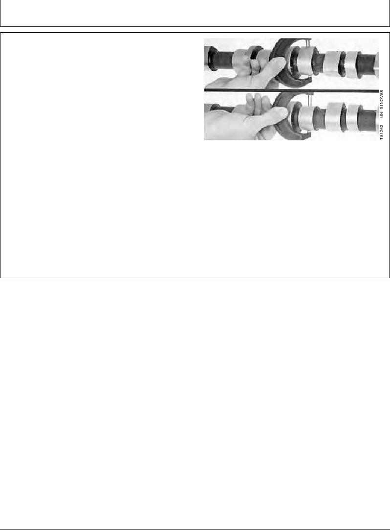
MEASURE CAMSHAFT LOBE LIFT
Measure each camshaft lobe at its highest point and at its
narrowest point. Subtract narrowest dimension from
highest dimension to find camshaft lobe lift.
If camshaft lobe lift is not within the wear specification on
any one lobe, install a new camshaft.
Intake Camshaft Lobe--Specification
Lift ........................................................ 7.69--7.79 mm (0.303--0.307 in.)
Wear Limit .................................................................. 7.19 mm (0.283 in.)
Measuring Camshaft Lobes
Exhaust Camshaft Lobe--Specification
Lift ........................................................ 8.25--8.35 mm (0.325--0.329 in.)
Wear Limit .................................................................. 7.75 mm (0.305 in.)
RG,RG34710,1208
1923OCT971/1