
TM 5-3805-281-24-2
Camshaft and Timing Gear Train
IMPORTANT: Oil holes in bushings and cylinder
block must be aligned after installation
or oil starvation will occur. The
elongated hole in bushing must be
toward the top. After installation, use a
small mirror with extension to be sure
oil holes are properly aligned.
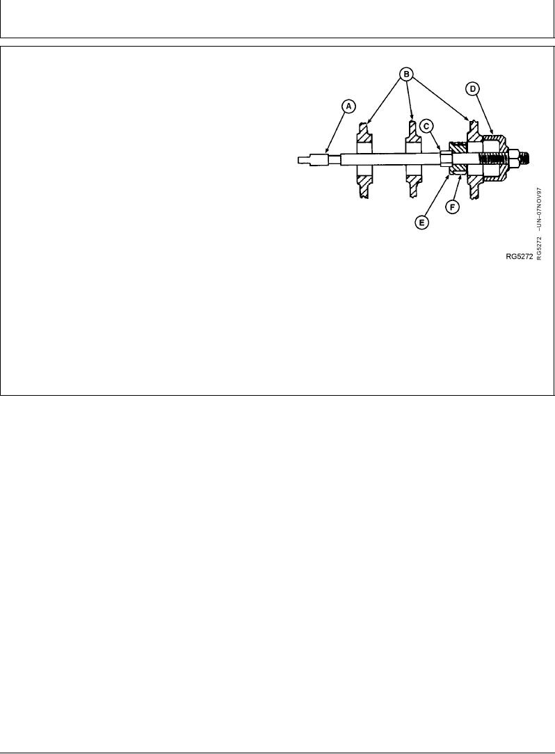
4. Slide a new camshaft bushing (F) onto JDG603
Bushing Driver (E). Assemble driver and JDGF604
Receiver Cup (D) along with components shown from
JDE6 Camshaft Bushing Replacement Set (A and C).
5. Be sure bushing is started square in bore and oil holes
are aligned with holes in block. Tighten nut to pull
bushing in until it is properly positioned in bore.
Installing Camshaft Bushings
6. Check bushing-to-cylinder block oil hole alignment
using a small mirror with extension.
A--Bushing Screw (JDE6-1)
B--Cylinder Block Web
C--Lock Bushing (No. 25916)
D--Receiver Cup (JDG604)
E--Bushing Driver (JDG603)
F--Camshaft Bushing
DPSG,OUOE003,29 1918DEC982/2
11-273