
TM 5-3805-281-24-2
Lubrication System
REMOVE, INSPECT, AND INSTALL ENGINE
OIL COOLER
Refer to ENGINE OIL COOLER ASSEMBLY, earlier in
this group for exploded view of engine oil cooler
assembly.
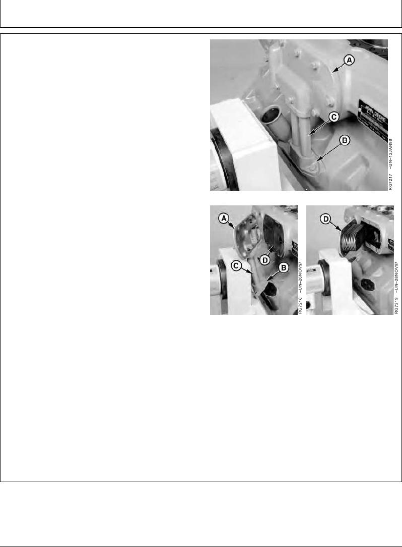
REMOVE OIL COOLER ASSEMBLY:
1. Remove eight cap screws securing oil cooler cover (A).
2. Remove two cap screws securing oil cooler tube
adapter (B). Remove cover, tubes (C), and adapter as
an assembly.
3. Remove oil cooler (D) from block bore. Clean all
gasket material from mating surfaces.
Removing Oil Cooler
INSPECT OIL COOLER ASSEMBLY:
1. Inspect oil cooler for physical damage, plugging, or
leakage which may allow mixing of oil and coolant.
2. Back flush oil cooler to clean all debris from core.
3. Pressure test oil cooler in liquid and compressed air if
mixing of oil and coolant is suspected.
Oil cooler should show no leakage when 140-170 kPa
(1.4--1.7 bar) (20--25 psi) air pressure is applied for a
minimum of 30 seconds.
Oil Cooler Removed
A--Oil
Cooler Cover/Bypass Valve Housing
4. Inspect all remaining parts of oil cooler assembly.
B--Oil
Cooler Tube Adapter
C--Oil
Cooler Tubes
Replace parts as needed. DO NOT attempt to repair oil
D--Oil
Cooler
cooler.
Continued on next page
RG,RG34710,1219
1923OCT971/2