
TM 5-3805-294-10
0020
INSTALLING IMPACT BREAKER - Continued
HYEX03406
13
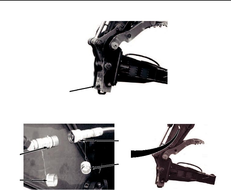
Figure 9.
Safety Pin to Lock Position.
20.
Clean cap (Figure 10, Item 14) and machine quick disconnect (Figure 10, Item 15) with rag.
17
15
16
14
HYEX01322
Figure 10. Connect Auxiliary Supply Line.
21.
Clean plug (Figure 10, Item 16) and attachment quick disconnect (Figure 10, Item 17) with rag.
22.
Remove cap (Figure 10, Item 14) from machine quick disconnect (Figure 10, Item 15).
23.
Remove plug (Figure 10, Item 16) from attachment quick disconnect (Figure 10, Item 17).
24.
Connect attachment quick disconnect (Figure 10, Item 17) to machine quick disconnect (Figure 10, Item 15).
25.
Clean plug (Figure 11, Item 18) and machine quick disconnect (Figure 11, Item 19) with rag.