
TM 5-3805-294-10
0092
DISCHARGE ADJUSTMENT - Continued
3
5
6
11
7, 8, 9
10
HYEX03094
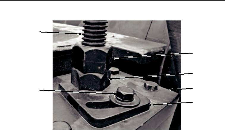
Figure 3.
Clamp Installation.
9.
Install clamp (Figure 3, Item 10) on plate (Figure 3, Item 11) with bolt (Figure 3, Item 7), lockwasher (Figure 3,
Item 8), and washer (Figure 3, Item 9).
10.
Using wrench provided with crush-all tighten nut (Figure 3, Item 5) against nut (Figure 3, Item 6) on rod (Figure
3, Item 3).
11.
Tighten nut (Figure 4, Item 2) and compress spring (Figure 4, Item 4) to align marks (Figure 4, Item 15) and
(Figure 4, Item 16).