
TM 5-3805-294-23-4
0611
REMOVAL - Continued
2
7
6
4
5
13
8
HYEX01662
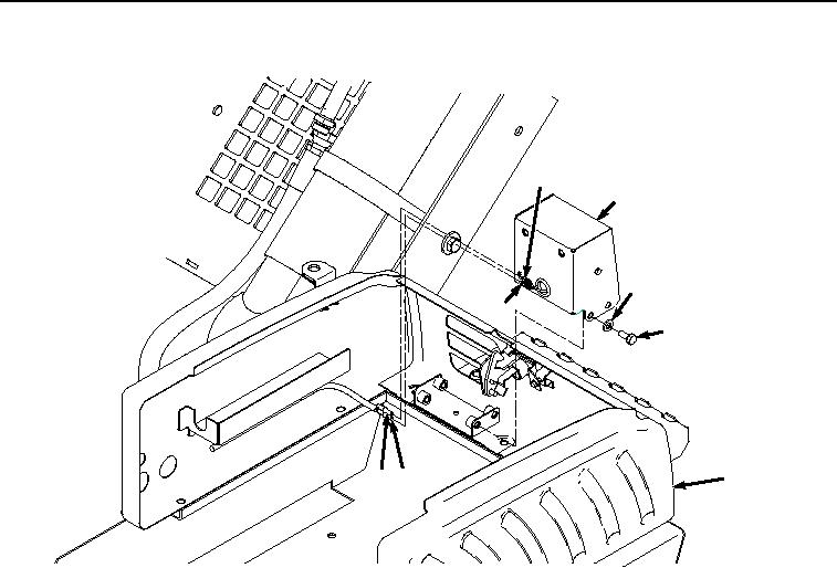
Figure 1. Light Removal.
2.
Remove machine wiring harness connector (Figure 1, Item 3) from drive light wiring connector (Figure 1, Item
4).
3.
Remove three screws (Figure 1, Item 5), washers (Figure 1, Item 6), and light assembly (Figure 1, Item 7) from
tool box (Figure 1, Item 8).
4.
Remove five screws (Figure 2, Item 9), washers (Figure 2, Item 10), and tool box (Figure 2, Item 8) assembly
from frame (Figure 2, Item 11).