
TM 5-3805-294-23-4
0611
DISASSEMBLY - Continued
22
21
14
20
19
25
24
23
HYEX01666
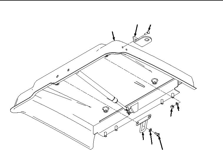
Figure 5.
Hasp Removal.
5.
Remove two screws (Figure 5, Item 21) and upper hasp (Figure 5, Item 22) from tool box lid (Figure 5, Item
14).
6.
Remove two screws (Figure 5, Item 23), washers (Figure 5, Item 24), and catch (Figure 5, Item 25) from tool
box lid (Figure 5, Item 14).
7.
Remove isolator (Figure 6, Item 26) from tool box lid (Figure 6, Item 14).