
TM 5-3805-294-23-4
0611
DISASSEMBLY - Continued
32
8
31
30
33
34
35
36
39
39
38
HYEX01668
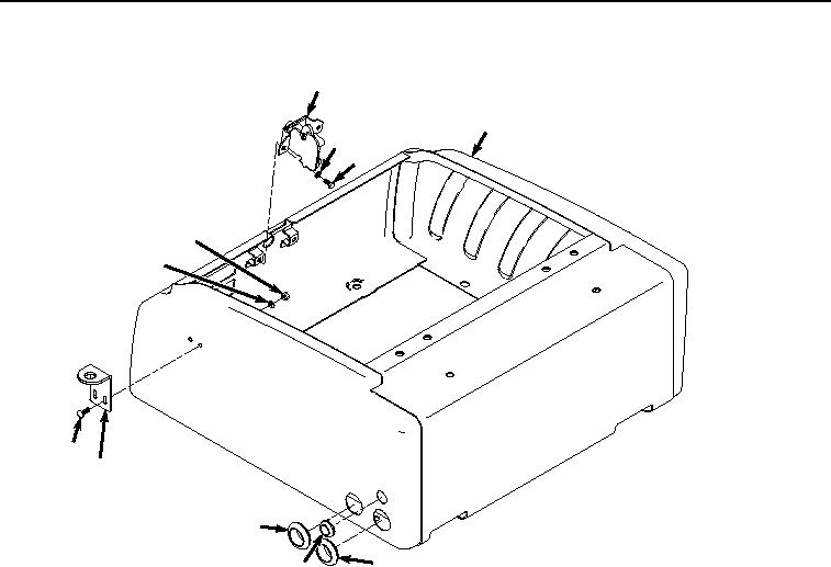
Figure 7.
Lock Removal.
10.
Remove two nuts (Figure 7, Item 33) and washers (Figure 7, Item 34) from screws (Figure 7, Item 35).
11.
Remove two screws (Figure 7, Item 35) and lower hasp (Figure 7, Item 36) from tool box (Figure 7, Item 8).
12.
Remove grommet (Figure 7, Item 38) from tool box (Figure 7, Item 8).
13.
Remove two grommets (Figure 7, Item 39) from tool box (Figure 7, Item 8).
END OF TASK
ASSEMBLY
1.
Install two grommets (Figure 8, Item 39) to tool box (Figure 8, Item 8).