
TM 5-3805-294-23-4
0611
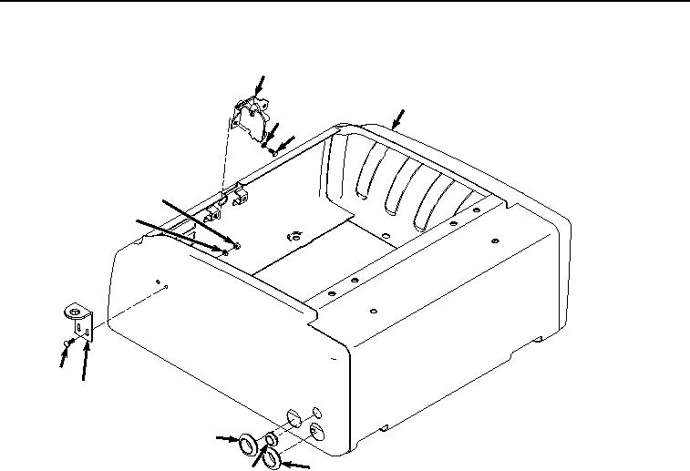
ASSEMBLY - Continued
32
8
31
30
33
34
35
36
39
39
38
HYEX01668
Figure 8. Lock Installation.
2.
Install grommet (Figure 8, Item 38) to tool box (Figure 8, Item 8).
3.
Position two screws (Figure 8, Item 35) and lower hasp (Figure 8, Item 36) to tool box (Figure 8, Item 8).
4.
Install two washers (Figure 8, Item 34) and nuts (Figure 8, Item 33) to screws (Figure 8, Item 35).
5.
Install lock assembly (Figure 8, Item 32) to tool box (Figure 8, Item 8) with two washers (Figure 8, Item 31) and
screws (Figure 8, Item 30).
6.
Install ram (Figure 9, Item 29) to tool box lid (Figure 9, Item 14) with two washers (Figure 9, Item 28) and pins
(Figure 9, Item 27).