• Home
  • Download PDF
  • Order CD-ROM
  • Order in Print
Figure 9. Ram and Isolator Installation.
Figure 11. Cover Installation.

Maintenance Manual For Hydraulic Excavator Type 1 With Hydraulic Thumb And Quick Latch -4 Page Navigation
  859    860    861    862    863  864  865    866    867    868    869  
img
.
TM 5-3805-294-23-4
0611
ASSEMBLY - Continued
22
21
14
20
19
25
24
23
HYEX01666
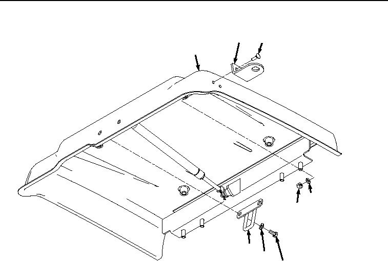
Figure 10. Hasp Installation.
12.
Position hasp (Figure 10, Item 22) to tool box lid (Figure 10, Item 14) with two screws (Figure 10, Item 21).
13.
Install two washers (Figure 10, Item 20) and nuts (Figure 10, Item 19) to screws (Figure 10, Item 21).
14.
Install seal (Figure 11, Item 18) to tool box lid (Figure 11, Item 14).
0611-11


Privacy Statement
Press Release
Contact

© Copyright Integrated Publishing, Inc.. All Rights Reserved.